Heat insulating wall member, and method of manufacturing the same

a technology of heat insulation wall and member, which is applied in the field of wall, can solve the problems of limited outside frame size of the container, wall to receive a bending or torsional load, and film may be torn, and achieve the effect of high heat insulation performan

Inactive Publication Date: 2005-03-01
ISUZU MOTORS LTD
View PDF17 Cites 123 Cited by
  • Summary
  • Abstract
  • Description
  • Claims
  • Application Information

AI Technical Summary

Benefits of technology

Therefore, in order to solve the above-mentioned problems, the present invention provides a wall structure for a heat insulating container of a vehicle, adopting a wall structure including a vacuum insulation panel mounted in a predetermined posit

Problems solved by technology

However, the outer frame size of the container is limited by regulations.
1) During transportation of the heat insulating travel container, the container is vibrated and deformed when traveling on a rough path or riding over a curbstone or the like, and this causes the wall to receive a bending or torsional load.
When such a load is added to the wall, the stress will be directly transmitted to the vacuum insulation panel, and the intensity of the film may not bear such stress.
As a result, the film may be torn.
When the film is tom, the panel can no longer maintain a vacuum condition, and the heat insulating performance of the vacuum insulation panel is deteriorated.
At this time, there is fear that the claws of the forklift may bump into the insulating wall, or obstacles outside the container may hit the wall, causing damage to the outer panel.
If the vacuum insulation panel is positioned close to the outer or inner panels of the insulating wall, damage to the panels may cause the film to break, and the insulating performance of the vacuum insulation panel may be deteriorated.
In this case, the vacuum insulation panel placed within the model for injection tended to move around the mold due to the expanding pressure of the urethane material, and it was very difficult to fix the vacuum panel in a determined position at the c

Method used


Image

  • Heat insulating wall member, and method of manufacturing the same
  • Heat insulating wall member, and method of manufacturing the same
  • Heat insulating wall member, and method of manufacturing the same

Examples


embodiment 1

(Embodiment 1)

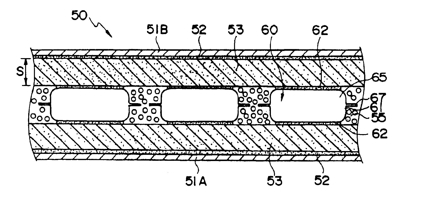
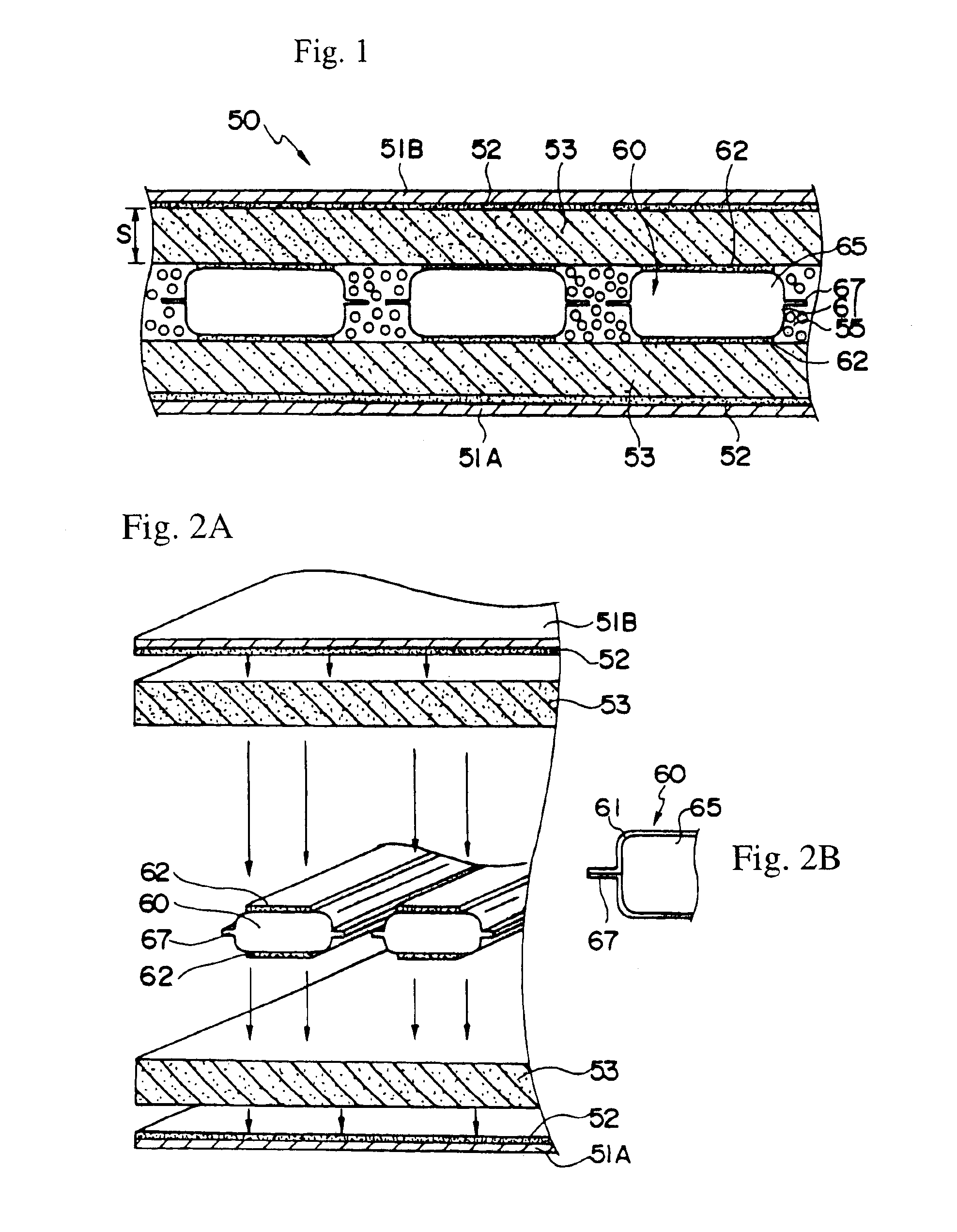
FIG. 1 shows a cross-sectional view of a wall according to the first embodiment of the present invention. FIGS. 2A and 2B show the structure of that wall.

A wall 50 comprises a first panel 51A and a second panel 51B acting as an outer panel and an inner panel, slab material members 53 made of a heat insulating material, and a vacuum insulation member 60.

The plate-shaped slab material members 53, having a heat insulating effect are adhered to the first panel 51A and the second panel 51B. The plate-shaped slab material members 53 are made of hard-type plastic foam such as styrene foam or urethane foam. The thickness S of each material member 53 is equal to or greater than the size of a base hole plus a clearance amount a. For example, if the size of the base hole is 15 mm and the clearance amount (a) is 10 mm, the size S is equal to or greater than 25 mm.

An adhesive 52 for the first and second plates 51A, B and the slab material members 53 may be thermoplastic adhesive (v...

embodiment 2

(Embodiment 2)

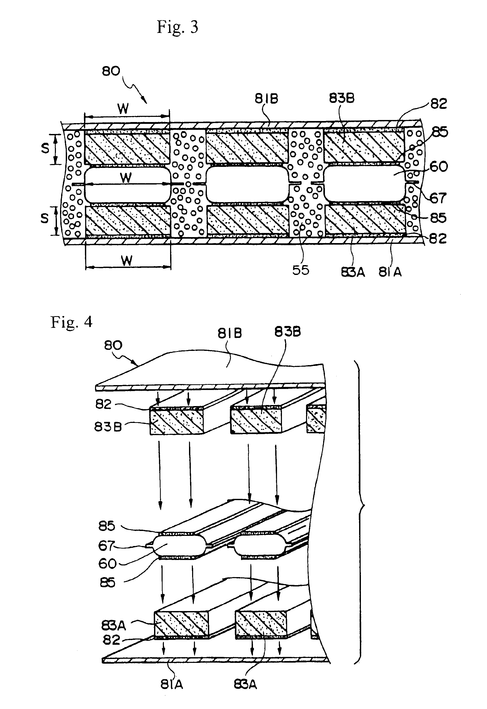
The present embodiment provides another wall structure capable of fixing the vacuum insulation member to a predetermined position, and a method of manufacturing the same (refer to FIGS. 3 and 4).

The wall 80 shown in the present embodiment includes vacuum insulation members 60 sandwiched by slab materials 83 having roughly the same size as the vacuum insulation members.

The method of manufacturing the wall 80 will now be explained.

(1) A plurality of pillar-shaped first slab (insulating) material members 83A formed of hard plastic foam with a thickness S (for example, 25 mm) and a width W equal to the width W of the vacuum insulation member 60 are adhered to the first panel 81A acting as the outer panel.

The first slab material members 83A are positioned at appropriate intervals.

The adhesive 82 is either applied only to the adhesion surface of the first slab material members 83A, or to the whole surface of the first panel 81A.

(2) The adhesive 85 is applied on the first sla...

embodiment 3

(Embodiment 3)

The present embodiment includes sandwiching the vacuum insulation member with slab materials, and forming a unit.

The method of manufacturing the wall according to the present embodiment will now be explained with reference to FIG. 5.

(1) The vacuum insulation member 60 is sandwiched, via an adhesive, by pillar-shaped first and second slab material members 93A and 93B, both having the same width size as the width W of the vacuum insulation member 60 and a thickness S. Then, pressurized adhesion is performed thereto.

Thereby, a unit 90U formed by sandwiching the vacuum insulation unit 60 with hard plastic foam slab material members 93A and 93B is completed.

(2) The adhesive is applied to both sides of the unit 90U. The first panel 91A is a pressurized and adhered to the first slab material member 93A, and a second panel 91B is pressurized and adhered to the second slab material member 93B. The adhesive may be applied to the adhering side of the first and second panels 91A a...


PUM


Abstract

A heat insulating wall, and a method of manufacturing the same. A laminated body includes a first panel, a first plate-shaped insulating member made of plastic foam and having a predetermined thickness, a vacuum insulation member mounted on the insulating member, a second plate-shaped insulating member made of plastic foam, and a second panel. The area between the first and second panels surrounded by the first plate-shaped insulating member, the vacuum insulation member, and the second plate-shaped insulating member is filled with expanded plastic foam. The thickness of the first and second plate-shaped insulating members is set to a predetermined thickness S.

Description

FIELD OF THE INVENTIONThe present invention relates to a wall including a vacuum insulation panel (member) to be used in a heat insulating transportation container of a vehicle, enabling cold reservation and refrigeration.BACKGROUND OF THE INVENTION(1) As shown in FIG. 14, a heat insulating wall 13 of a body 15 in a refrigeration vehicle or cold reservation vehicle 10 typically has the structures disclosed in the following:a. A sandwich panel 13A formed by adhering a slab 131, made of expanded urethane foam or expanded styrene foam or the like (already expanded and formed into a plate-shape), to inner and outer panels 13a, 13b, made of a plate-shaped flattened aluminum material, FRP, or steel, by use of an adhesive 13c; orb. A panel 13B shown in FIG. 15, where an independent expanding urethane resin is injected and expanded between inner and outer panels 13a, 13b to form a portion 133, and the inner and outer panels are bonded with the self-adhering force of urethane.Normally, the h...

Claims


Application Information

Patent Timeline
IPC IPC(8): B62D33/00B62D33/04E04B1/80
CPCB62D33/048E04B1/803Y02B80/12Y02A30/242Y02B80/10F25D2201/14
Inventor YAMAMOTO, NAOTAKAKITOU, SEIICHIRO
Owner ISUZU MOTORS LTD
Why Eureka
Try Eureka