Centrifugal compressor wheel

a centrifugal compressor and impeller technology, which is applied in the direction of machines/engines, mechanical equipment, liquid fuel engines, etc., can solve the problems of reducing weakening the structural integrity of the blade, and prone to stalling of the wing, so as to reduce the efficiency of the blade to move air, minimize blockage and reverse flow, and reduce the effect of blade sli

Inactive Publication Date: 2005-03-01
BORGWARNER INC
View PDF8 Cites 20 Cited by
  • Summary
  • Abstract
  • Description
  • Claims
  • Application Information

AI Technical Summary

Benefits of technology

As a result of his background in aerospace engineering and his familiarity with attempts to avoid stall and choke in turbocharger systems, the inventor realized that a slit in the compressor blade might be beneficial. However, the inventor was also aware of the limitations involved with introducing a slit into a compressor blade. Introducing slits into compressor blades would seem to weaken the structural integrity of the blade and reduce the efficiency of the blade to move air.
By introducing some of the air from the pressure side of the blade to the suction side of the blade through a slit in the blade, the inventor was able to reenergize the boundary layer. This allows the boundary layer to stay attached, minimizing blockage and reverse flow. Various shapes, positions, lengths and widths, locations, and arrangements of either a slit or a series of perforations on the compressor blade can be used to accomplish this objective.
This invention accomplishes the objectives of avoiding surge conditions by prolonging the boundary layer adherence to the suction side of the compressor blade, by maintaining a low level of noise emission, and by continuing to provide ease of manufacturing. There is also no significant reduction in structural integrity, and the benefits of the slit feature outweigh any reduction in the structural integrity. Further, because the air does not have to be recirculated, all of the air already in the compressor is used more efficiently.

Problems solved by technology

Under these conditions, the wing is prone to stall because lift force is lost due to the separation of the boundary layer over the suction surface of the wing.
However, the inventor was also aware of the limitations involved with introducing a slit into a compressor blade.
Introducing slits into compressor blades would seem to weaken the structural integrity of the blade and reduce the efficiency of the blade to move air.

Method used


Image

  • Centrifugal compressor wheel
  • Centrifugal compressor wheel
  • Centrifugal compressor wheel

Examples


Embodiment Construction

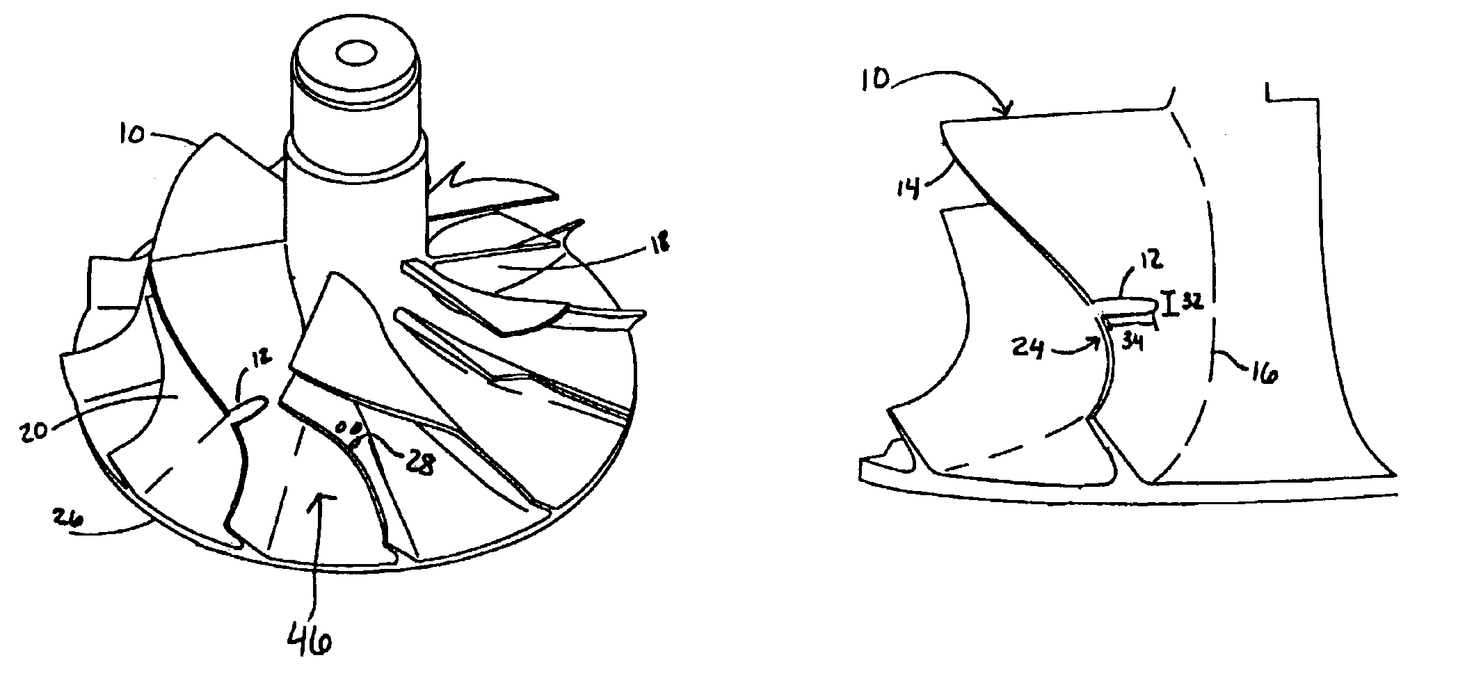
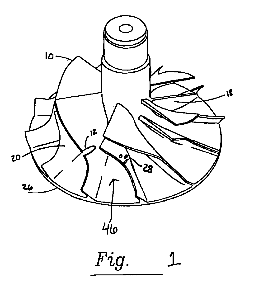
FIG. 1 shows a compressor wheel according to the prior art. The air is trapped between the blades 10 and the compressor wheel hub 26 in an area called airflow channels 46. The suction side of the blade 20 is the area of low pressure, and the pressure side of the blade 18 is the area of high pressure. As the air passes through the airflow channels 46, boundary layers build up on the blade surfaces. These low momentum masses of air are considered a blockage and cause surge conditions. Ultimately, the boundary layer on the suction side of the blade 20 will separate, causing stall and reversed flow. This can be prevented, or at least delayed, by introducing some of the high-energy flow from the pressure side of the blade 18 into the low-energy side of the suction side of the blade 20 via a slit 12 or series of perforation 28 features.

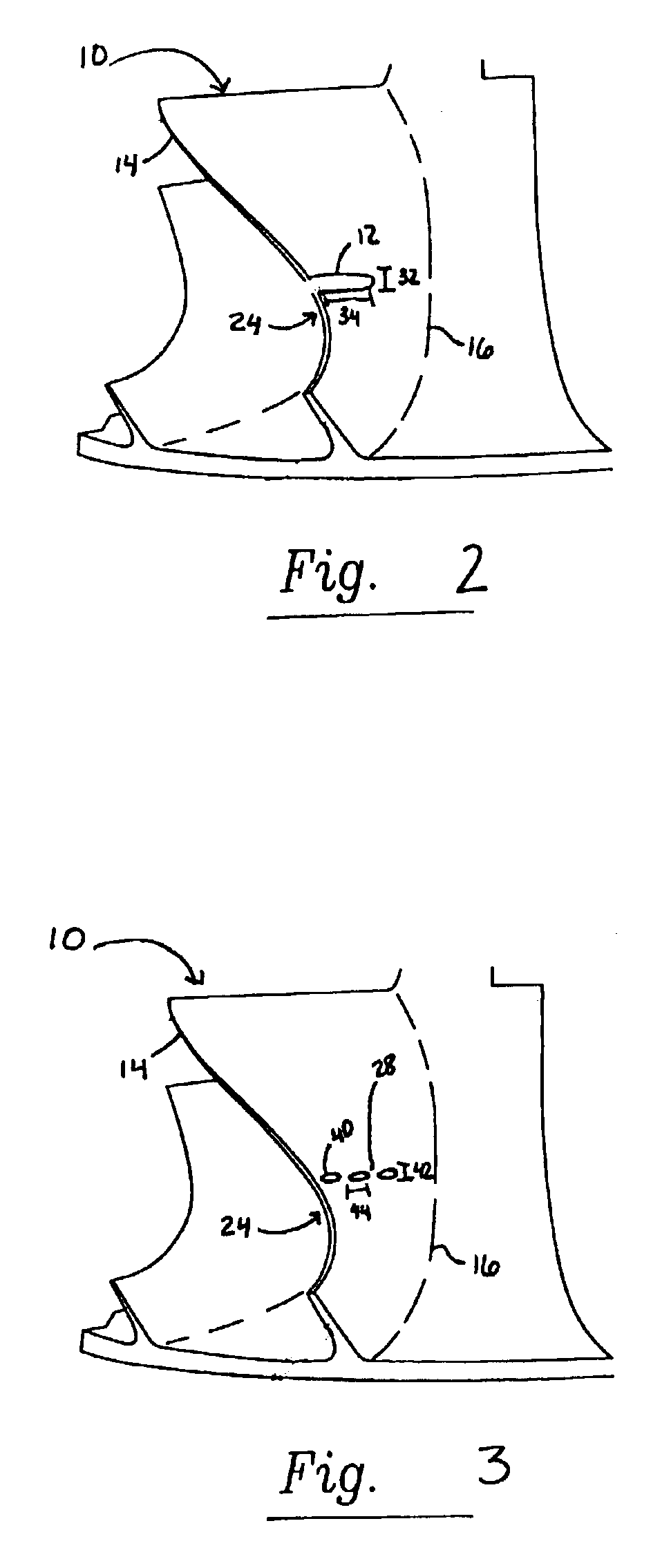
FIG. 2 depicts an elevated perspective view of a compressor impeller blade 10. The compressor impeller blade 10 is connected to the compressor wheel hub 26...


PUM


Abstract

As air passes through the airflow channels (46) between the blades (10) of a compressor impeller, boundary layers build up on the blade (10) surfaces. These low momentum masses of air are considered a blockage and loss generators. Ultimately, the boundary layer on the suction side of the blade (20) will separate, causing stall and reversed flow. Reversed flow will occur until a stable pressure ratio with positive volume flow rate is reached. When the pressure ratio becomes unstable again, the cycle will repeat. Introducing a slit (12) or a series of perforations (28) on the compressor wheel blade (10) allows the air to communicate between the pressure side (18) and the suction side (20) of the blade, which allows the boundary layer to stay attached longer. The invention allows for various shapes, positions, lengths and widths, locations, and arrangements of either a slit (12) or a series of perforations (28) on the compressor blade (10) in order to accomplish the objectives of delaying surge conditions by prolonging the boundary layer adherence to the suction side (20) of the compressor blade (10) and of maintaining a low level of noise emission, ease of manufacturing, and structural integrity.

Description

FIELD OF THE INVENTIONThe present invention concerns a compressor impeller wheel for use in turbochargers on internal combustion engines and more particularly to a design modification to reduce surge associated with airflow.BACKGROUND OF THE RELATED ARTTurbochargers are widely used on internal combustion engines, and in the past have been particularly used with large diesel engines, especially for highway trucks and marine applications. Compressor impeller wheels are found in both superchargers, which derive their power directly from the crankshaft of the engine, and turbochargers, which are driven by the engine exhaust gases.More recently, in addition to use in connection with large diesel engines, turbochargers have become popular for use in connection with smaller, passenger car power plants. The use of a turbocharger in passenger car applications permits selection of a power plant that develops the same amount of horsepower from a smaller, lower mass engine. Using a lower mass e...

Claims


Application Information

Patent Timeline
Patent Type & Authority Patents(United States)
IPC IPC(8): F01D5/14F01D5/02F01D5/04F04D29/28F04D29/68F04D29/30F04D29/66
CPCF01D5/048F01D5/145F04D29/30F04D29/681F04D29/284Y10S415/914F04D29/684F04D29/682
Inventor SEKULARAC, ALEKSANDAR
Owner BORGWARNER INC
Why Eureka
Try Eureka