Socket for electrical parts having spacer

a technology of electrical parts and sockets, which is applied in the direction of securing/insulating coupling contact members, electrical discharge lamps, and coupling device connections, etc., can solve the problems of increasing production costs, prone to fluctuation of the contact pressure of the probe pin, and inability to perform stably the performance test of the ic packag

Inactive Publication Date: 2005-03-01
ENPLAS CORP
View PDF4 Cites 7 Cited by
  • Summary
  • Abstract
  • Description
  • Claims
  • Application Information

AI Technical Summary

Benefits of technology

An object of the present invention is to provide a socket for electrical parts by using a contactor-accommodating member which can be produced precisely by machine work such as cutting process etc. instead of molding using a mold die. Another object of the present invention is to provide a socket for electrical parts which can be used for IC packages having a large number of terminals and a narrow terminal pitch and capable of positioning and mounting a contactor precisely with respect to and on the electrode of the circuit board, the contactor being able to correspond to the terminal of the IC package having a large number of and a narrow pitch of the terminal.

Problems solved by technology

Therefore preparing a mold die which can only be used for producing a socket for electrical part to be made by the small-lot production may cause increase in production cost, being uneconomical.
In a case where the probe pin is installed in such conventional plates 1, 2 and used as a socket, there is a fear that performance test of the IC package can not be carried out stably and certainly because contact pressure of the probe pin tends to fluctuate and can not be controlled within a prescribed range.
If the burn-in testing is conducted under the condition that the probe pin is slightly misaligned from a prescribed position of the electrode of the circuit board, electrical connection between the probe pin and the electrode of the printed circuit board may not be established at worst.

Method used


Image

  • Socket for electrical parts having spacer
  • Socket for electrical parts having spacer
  • Socket for electrical parts having spacer

Examples


Embodiment Construction

A preferred embodiment of the present invention will be described hereunder with reference to the accompanying drawings.

In addition, it is to be noted that the terms “upper”, “lower”, “vertical”, “horizontal” and the like described herein are used in the illustrated state or usable state of the socket or members associated herewith and also that a number of contact pins, holes and terminals are actually arranged, though the description may be made with reference to single one thereof for the sake of easy understanding of the present invention.

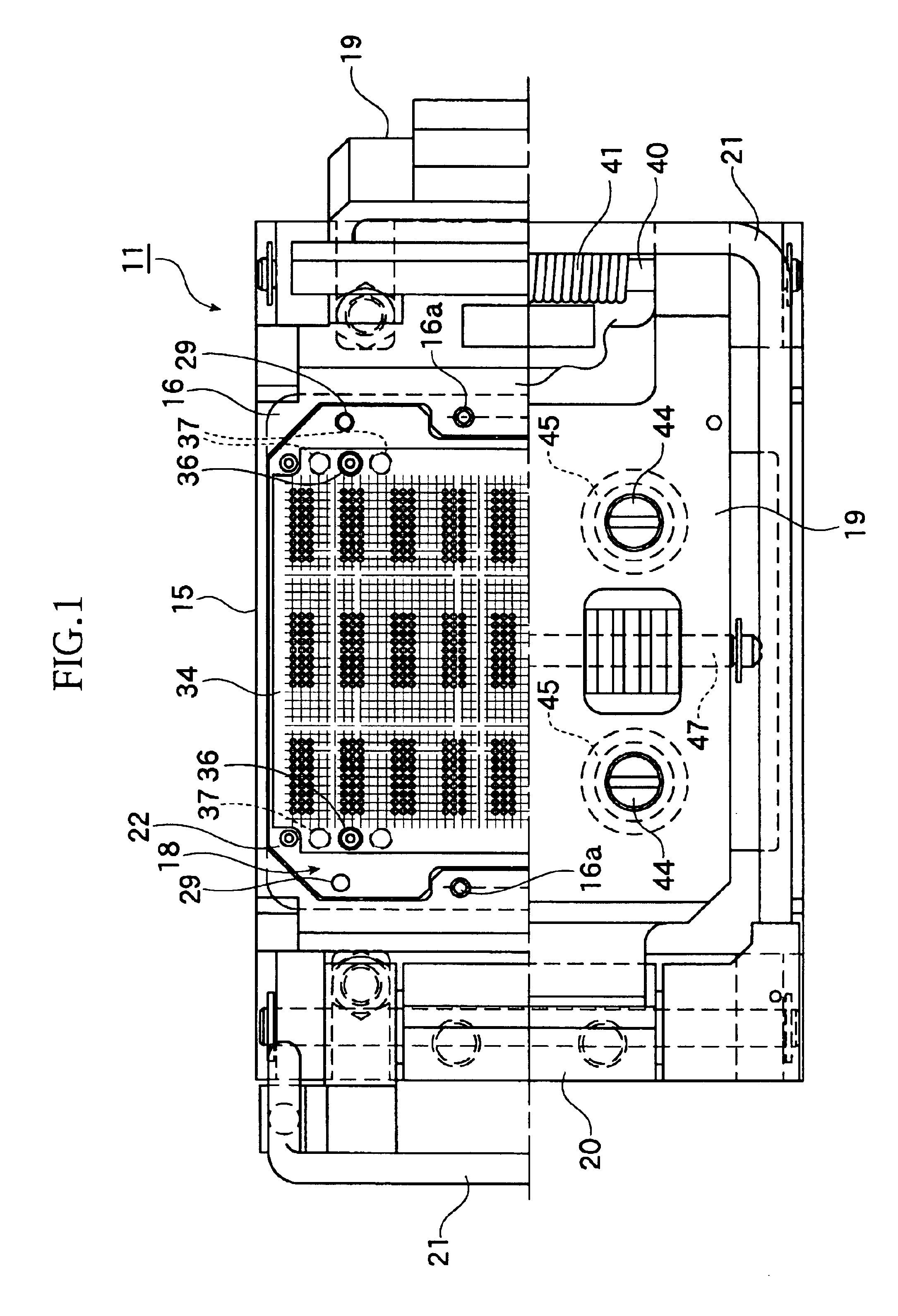
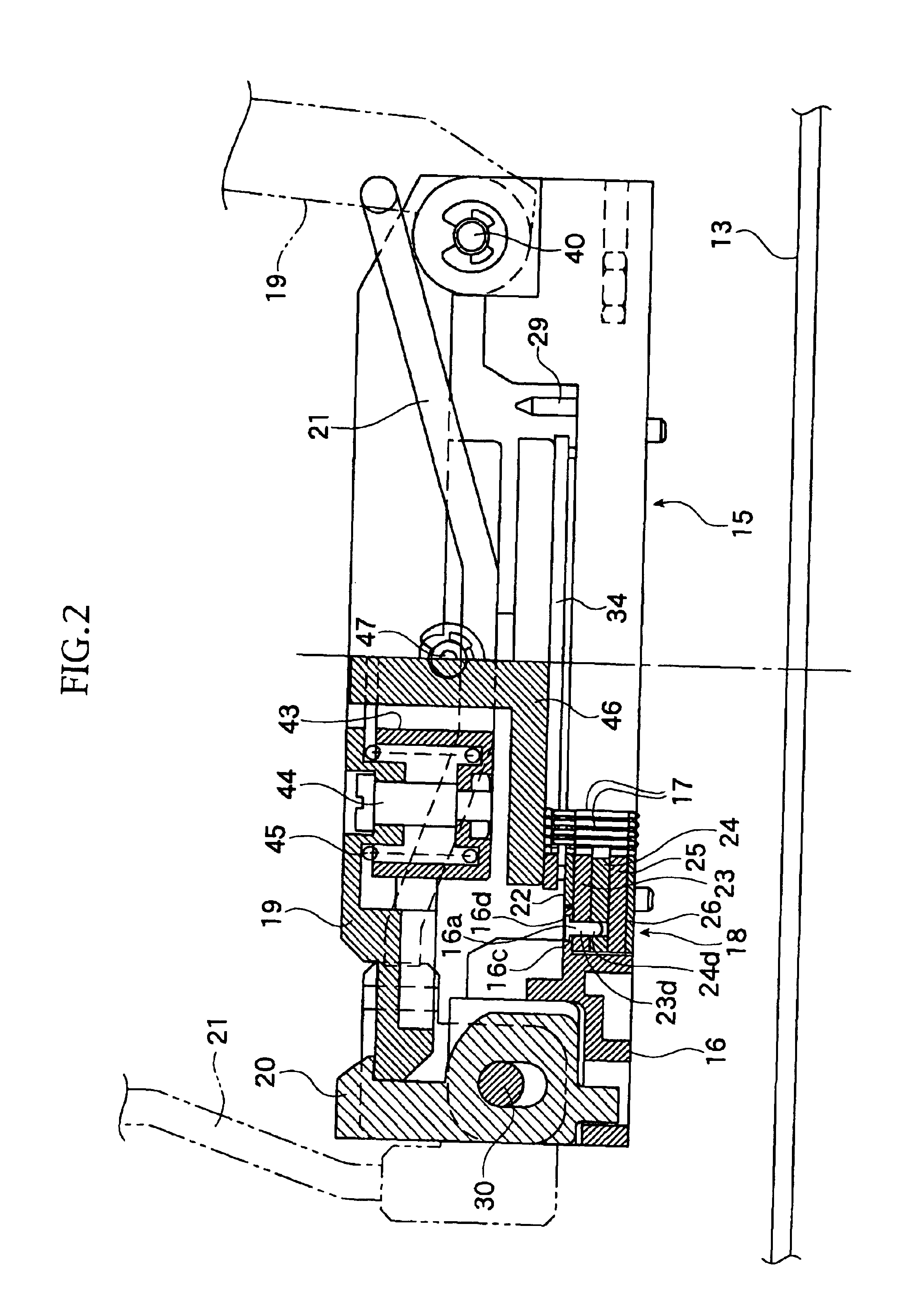
FIG. 1 to FIG. 17B show the embodiments of the present invention.

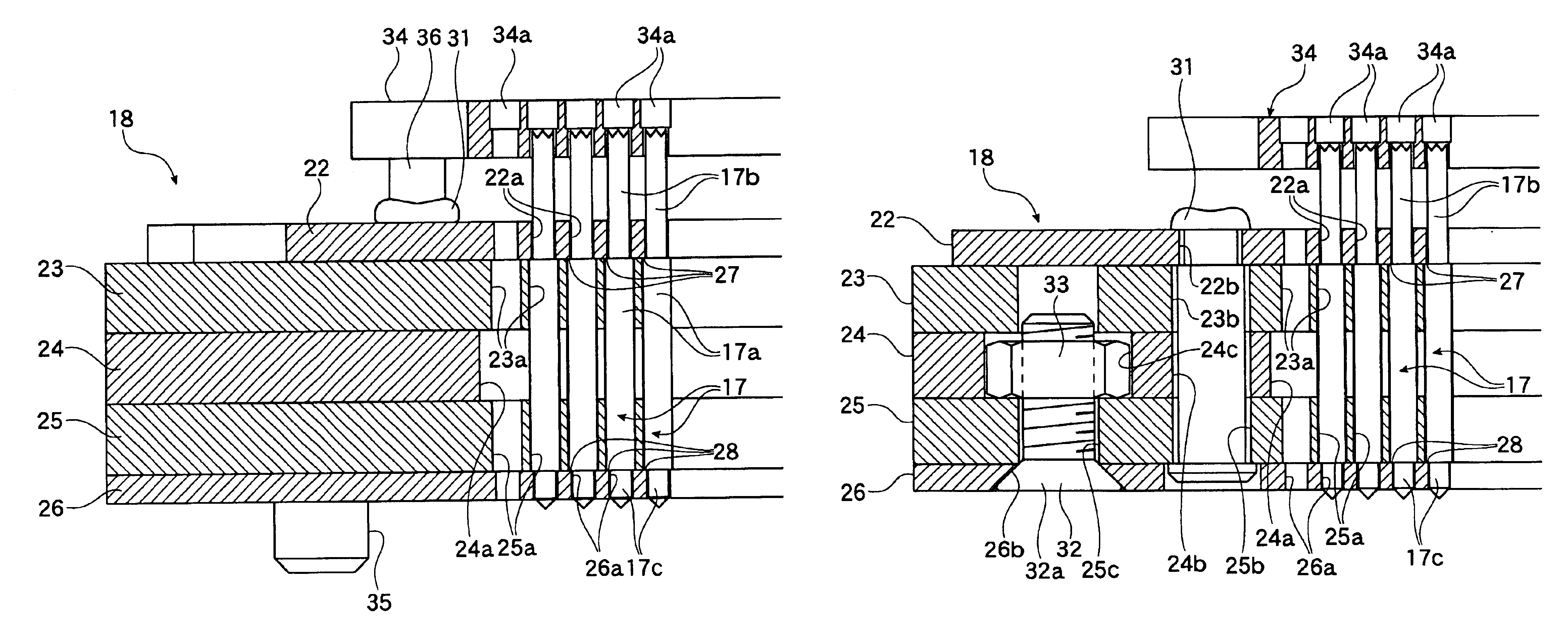
First, configuration of the socket will be explained. Reference numeral 11 is an IC socket as “socket for electrical parts.” This IC socket is what is called a clam shell type and is used for conducting electrical performance test for IC package as “electrical part.”

And this IC socket is used for connecting a terminal 12b of an IC package 12 and an electrode provided on a printed ...


PUM


Abstract

A socket for electrical parts, which is mounted on a circuit board, comprises a socket body on which the electrical part is accommodated, and a plurality of contactors disposed on the socket body for establishing an electrical connection between the circuit board and the electrical part. The socket body comprises a contact unit in which the contactors are held and the contact unit is comprised of plates to be superimposed. Each plate has a plurality of through holes through each of which the contactor is inserted. A hole size of the through holes of one plate being different from that of another plate which is directly disposed on the one plate so as to form a stepped portion between the through holes of the one plate and another plate. The stepped portion is used for preventing the contactor from coming off from the contact unit.

Description

BACKGROUND OF THE INVENTION1. Field of the InventionThe present invention relates to a socket for electrical parts for detachably accommodating and holding an electrical part such as a semiconductor device (called as “IC package” hereinlater), to conduct an electric performance test and examination of such electrical part.2. Related Art of the InventionAs a conventional “socket for electrical part,” there have been provided an IC socket for detachably holding an IC package as “electrical part.”The IC package includes, for example, one having a plurality of terminals on a lower surface of strip like package body.On a socket body of the IC socket, a plurality of probe pins are provided. The probe pin is designed to establish an electrical connection between a printed circuit board and the IC package terminal.As a conventional probe pin, there is, for example, one which comprises a vertically movable upper side contact member and a lower side contact member disposed at an upper and low...

Claims


Application Information

Patent Timeline
Patent Type & Authority Patents(United States)
IPC IPC(8): H01R12/16H01R12/00H01R13/40H01R13/405H01R33/74
CPCH01R12/7076H01R13/405H01R12/523
Inventor SHIMADA, HIDEO
Owner ENPLAS CORP
Why Eureka
Try Eureka