Method and apparatus for mounting a rotating reflector antenna to minimize swept arc

a technology of rotating reflectors and antennas, which is applied in the field of antenna systems, can solve the problems of increasing increasing the drag on aircraft, and increasing aircraft performance and fuel consumption, so as to reduce the frontal surface area of radomes and complicate assembly or construction.

Inactive Publication Date: 2005-03-01
THE BOEING CO
View PDF11 Cites 14 Cited by
  • Summary
  • Abstract
  • Description
  • Claims
  • Application Information

AI Technical Summary

Benefits of technology

A principal feature of the present invention is that the azimuthal axis about which the main reflector is rotated is disposed forwardly of the center of the main reflector, rather than at, or rearwardly of, the center of the main reflector. In one preferred form, the azimuthal axis is located at a point within a plane extending between the outermost ends of the main reflector. In another preferred embodiment, the azimuthal axis is located forwardly of the outer ends of the main reflector. With either arrangement, the swept arc of the main reflector is reduced from that which would otherwise be produced if the azimuthal axis was located coincident with the center of the main reflector, or rearwardly of the center of the main reflector. The maximum reduction in swept arc is provided by locating the azimuthal axis within the plane extending between the outermost ends of the main reflector.
By supporting the main reflector of the antenna at a position laterally offset (i.e., rearwardly) of the azimuthal axis about which the mounting platform is rotated, the swept arc of the antenna is reduced significantly, thereby decreasing the frontal surface area of a radome needed to house the antenna system when the system is mounted on an exterior surface of an aircraft. This mounting arrangement does not significantly complicate the assembly or construction of the antenna system itself or otherwise require significant modifications to the outer body surface of an aircraft on which the antenna system is to be mounted.

Problems solved by technology

This is because of the drag created by the radome and the resulting effects on aircraft performance and fuel consumption.
This necessitates a commensurately wide radome, thus increasing the frontal surface area of the radome and consequently increasing the drag on the aircraft.

Method used


Image

  • Method and apparatus for mounting a rotating reflector antenna to minimize swept arc
  • Method and apparatus for mounting a rotating reflector antenna to minimize swept arc
  • Method and apparatus for mounting a rotating reflector antenna to minimize swept arc

Examples


Embodiment Construction

The following description of the preferred embodiment(s) is merely exemplary in nature and is in no way intended to limit the invention, its application, or uses.

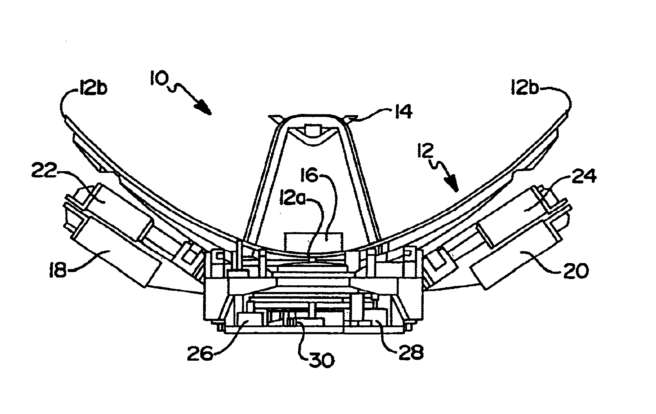
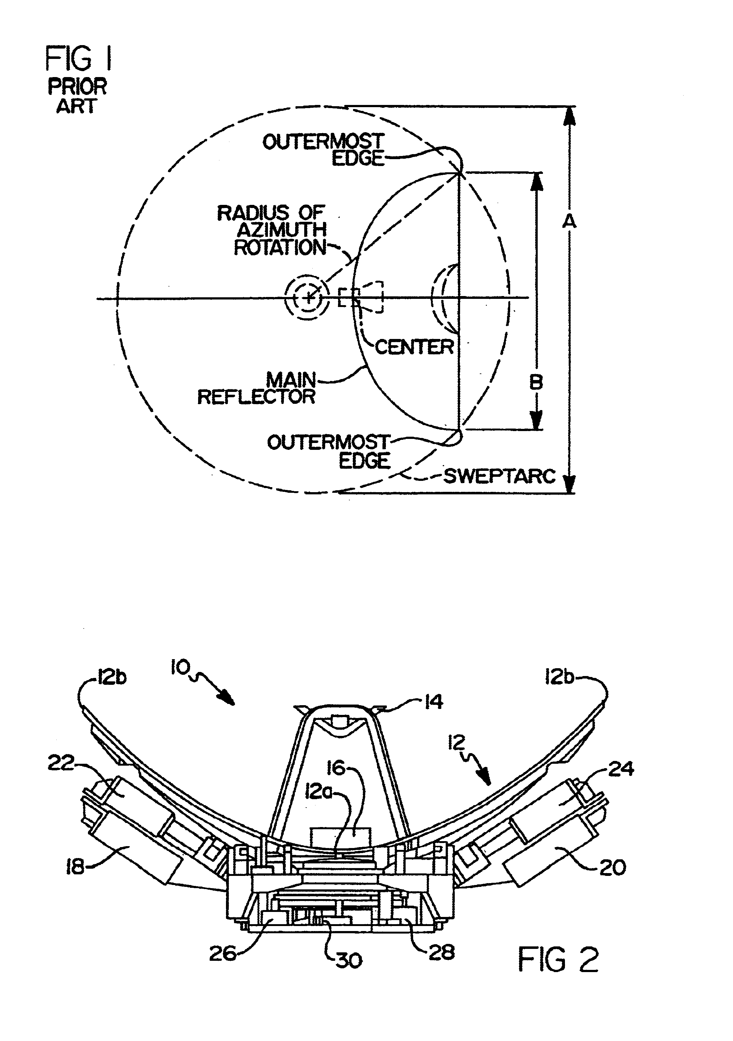
Referring to FIG. 2, a prior art antenna system 10 well suited to be mounted on an external surface of an aircraft is shown. The antenna system 10 includes a main reflector 12 having a center 12a and outermost edge portions 12b. A subreflector 14 is positioned forwardly of a feedhorn 16 located at the center 12a of the main reflector 12. A pair of low noise amplifiers (LNA) 18 and 20 are used, as are a pair of diplexers 22 and 24, for performing signal conditioning operations on the received and transmitted signals. An elevation motor 26 is used to position the main reflector 12 at a desired elevation angle, while an azimuth motor 28 is used to rotate the main reflector 12 about an azimuthal axis to position the main reflector at a desired azimuth angle. An encoder 30 is used to track the azimuth angle of the main reflector...


PUM


Abstract

An apparatus and method for mounting a reflector antenna system on an outer surface of an aircraft which minimizes a swept arc of a main reflector. This allows the effective frontal area of the main reflector to be reduced such that a radome with a smaller frontal area can be employed to cover the antenna system. The preferred embodiments make use of a platform which rotates the main reflector about an azimuthal axis which is disposed forwardly of an axial center of the main reflector. In one embodiment, the azimuthal axis is located in a plane extending between the outermost lateral edges of the main reflector. In another embodiment the azimuthal axis is located forwardly of the outermost lateral edges of the main reflector.

Description

FIELD OF THE INVENTIONThe present invention relates to antenna systems, and more particularly to a method and apparatus for mounting a reflector antenna in such a manner as to minimize the swept arc of the antenna when the antenna is rotated about its azimuthal axis.BACKGROUND OF THE INVENTIONThe frontal surface area of an antenna mounted on an aircraft, under a radome, is of critical importance with respect to the aerodynamics of the aircraft. This is because of the drag created by the radome and the resulting effects on aircraft performance and fuel consumption. With reflector antennas that must be rotated about their azimuthal axes, the “swept arc” of the antenna is larger than the overall width of the main reflector of the antenna. This necessitates a commensurately wide radome, thus increasing the frontal surface area of the radome and consequently increasing the drag on the aircraft.Referring to FIG. 1, the diameter of a swept arc “A” of a main reflector of a prior art antenna...

Claims


Application Information

Patent Timeline
Patent Type & Authority Patents(United States)
IPC IPC(8): H01Q3/04H01Q1/27H01Q3/02H01Q1/28
CPCH01Q3/04H01Q1/28
Inventor DESARGANT, GLEN J.BIEN, ALBERT LOUIS
Owner THE BOEING CO
Why Eureka
Try Eureka