

Transflective liquid crystal device and electronic apparatus using the same
- Summary
- Abstract
- Description
- Claims
- Application Information
AI Technical Summary
Benefits of technology
Problems solved by technology
Method used
Image

Examples
first exemplary embodiment
[First Exemplary Embodiment]
(Basic Structure of a Transflective Liquid Crystal Device)
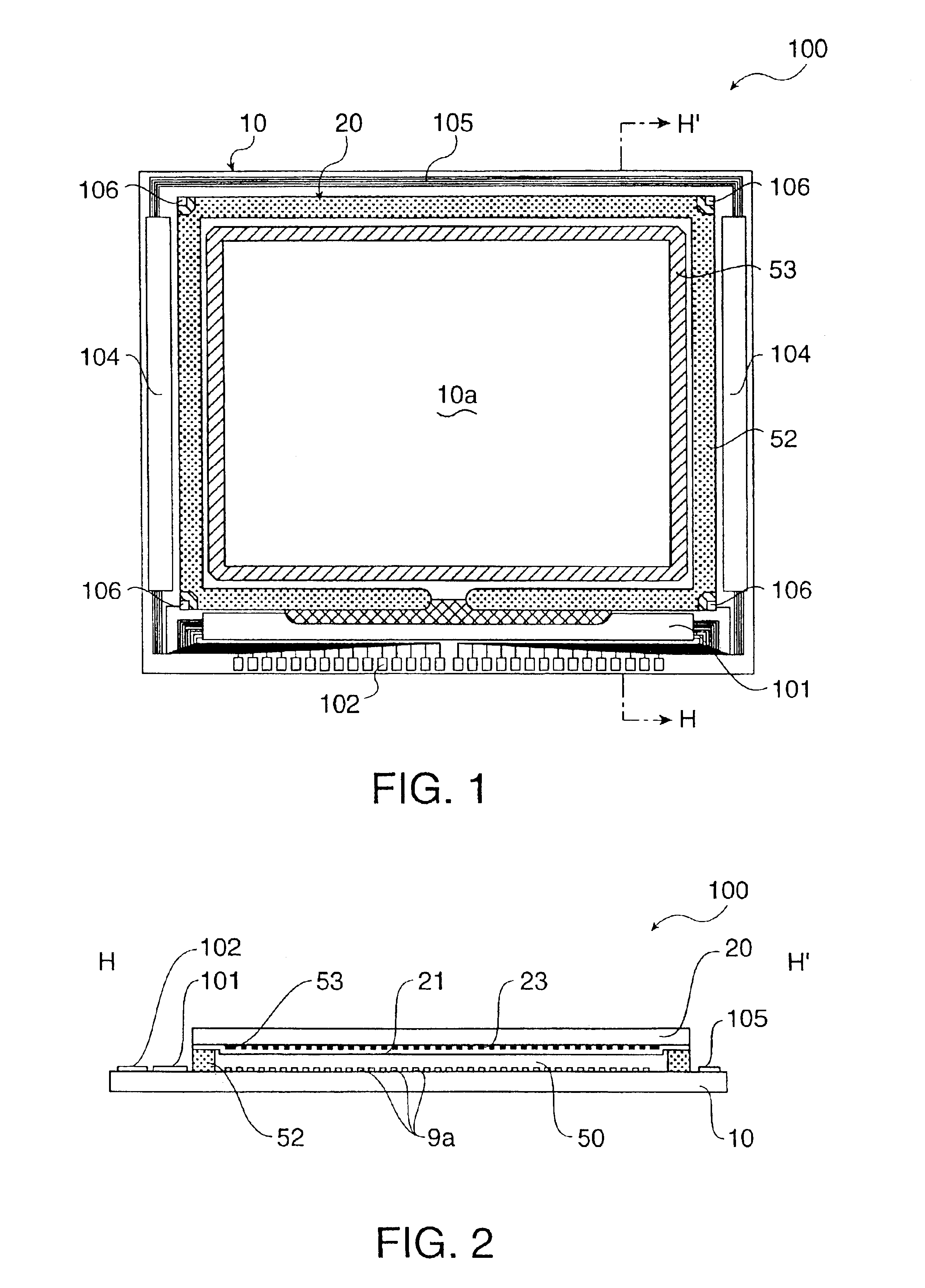
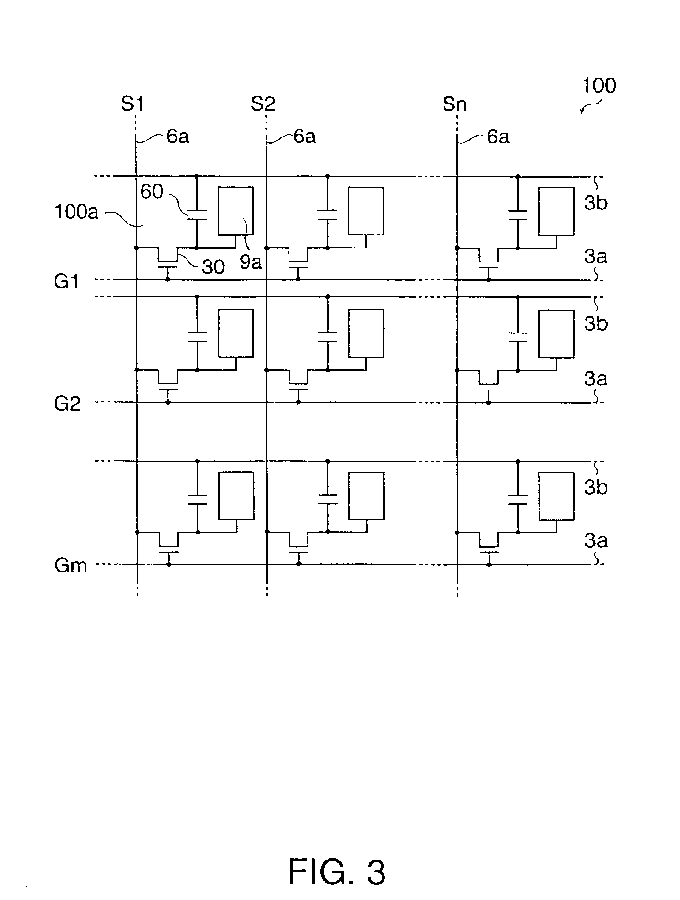
FIG. 1 is a plan view of a transflective liquid crystal device according to the present invention as viewed from component elements and a counter substrate, and FIG. 2 is a sectional view taken along plane H-H′ of FIG. 1. FIG. 3 is an equivalent circuit diagram showing component elements, wirings, etc. in a plurality of pixels formed in a matrix shape in the image display region of the transflective liquid crystal device. Further, in the following description, the scales of layers or members in the drawings are different since each layer or member is merely drawn with a size to be recognizable in the drawings.
As shown in FIGS. 1 and 2, a transflective liquid crystal device 100 of this exemplary embodiment is configured such that a liquid crystal layer 50 as an electric optical material is held between a TFT array substrate 10 (a first transparent substrate) and a counter substrate 20 (a second tran...
second exemplary embodiment
[Second Exemplary Embodiment]
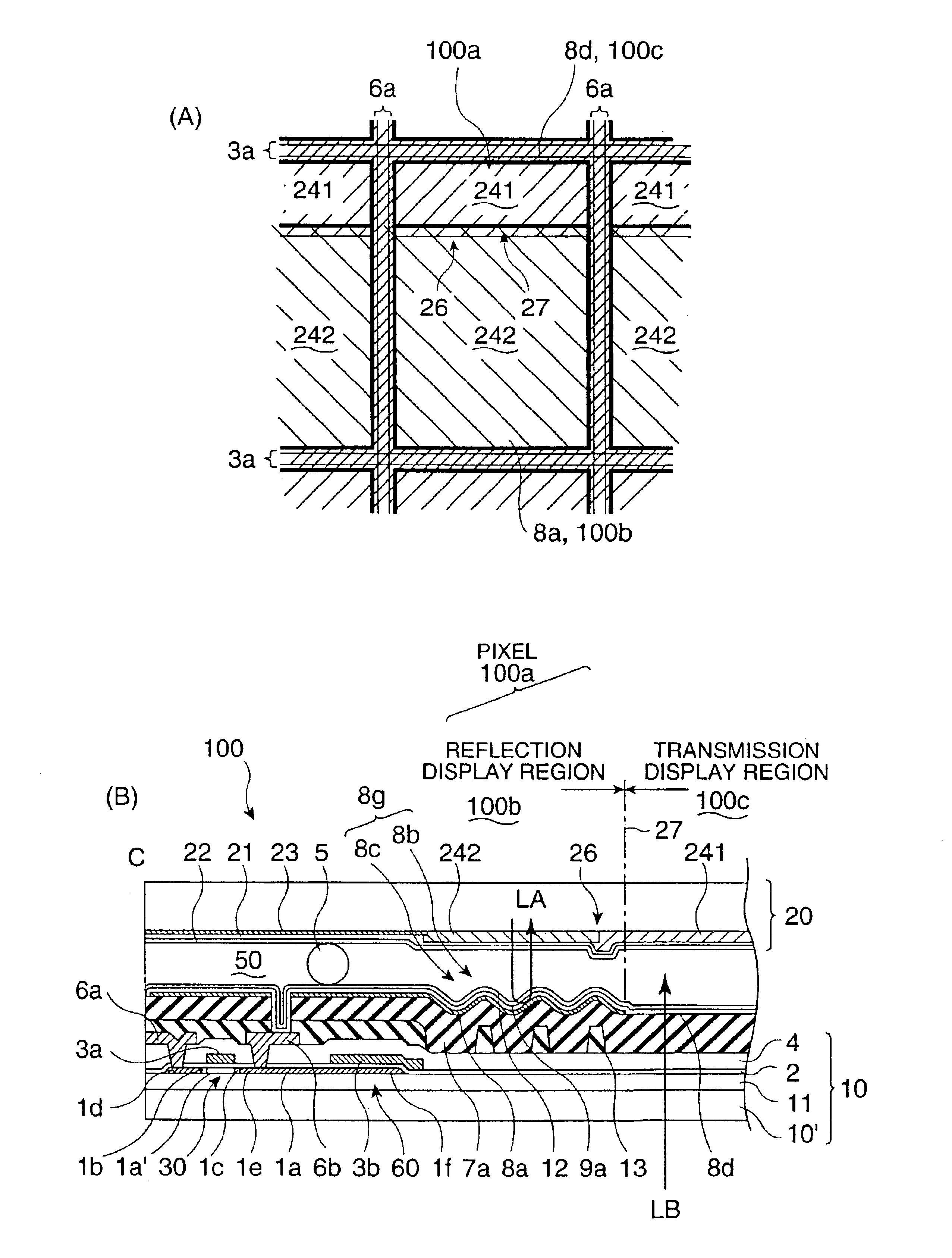
FIG. 6(A) is a schematic of a reflection display region and a transmission display region formed in the pixels of the transflective liquid crystal device according to a second exemplary embodiment, and FIG. 6(B) is a sectional view of a part of the pixel taken along plane C-C′ of FIG. 4. Further, in the configuration of this exemplary embodiment and any configuration to be described below, a basic structure is the same as that of the first exemplary embodiment. Therefore, the common elements will be designated with the same numeral so as to omit the description thereof, and only a counter substrate which is a feature of each exemplary embodiment is explained.
On the surface of a counter substrate 20 according to the exemplary embodiment as shown in FIGS. 6(A) and 6(B), the same as in the first exemplary embodiment, a color filter for reflection display 242 with a narrow chromaticity region is formed in a reflection display region 100b having a light refle...
third exemplary embodiment
[Third Exemplary Embodiment]
FIG. 7(A) is a typical explanatory view of reflection display region and a transmission display region formed in the pixel in the transflective liquid crystal device according to a third exemplary embodiment, and FIG. 7(B) is a sectional view of a part of the pixel taken along plane C-C′ of FIG. 4.
On the surface of a counter substrate 20 according to the exemplary embodiment as shown in FIGS. 7(A) and 7(B), the same as in the first exemplary embodiment, a color filter for reflection display 242 with a narrow chromaticity region is formed in a reflection display region 100b having a light reflecting film 8a formed thereon, and a color filter for transmission display 241 with a wide chromaticity region is formed in a transmission display region 100c having a light transmitting window 8d formed thereon. In the pixel 100a, a boundary portion 26 of the color filter for reflection display 242 and the color filter for transmission display 241 is extended paralle...
PUM
 Abstract
Description
Claims
Application Information