Bag sealing system and method

a bag sealing and bag closure technology, applied in the field of vacuum packaging, can solve the problems of contaminating packaged food products, affecting the quality of packaged food products, and affecting the sealing effect of the bag, and achieve the effect of increasing the thermal mass and low failure ra

Inactive Publication Date: 2005-03-08
PACKTECH
View PDF39 Cites 44 Cited by
  • Summary
  • Abstract
  • Description
  • Claims
  • Application Information

AI Technical Summary

Benefits of technology

It is, therefore, an object of the present invention to provide a constant temperature heat sealing device for vacuum packaging machines that avoids the problems of prior art impulse sealing devices such as oxidation of the element and mechanical stress due to rapid and frequent temperature fluctuations.
Another object of the present invention is to provide a continuous temperature heat-sealing device that works well using relatively large heating elements having an increased thermal mass.
It is a further object of the invention to provide a continuous temperature heat-sealing device that yields a relatively low failure (“leaker”) rate in sealed bags.

Problems solved by technology

A significant problem in food packaging applications relates to “leakers”, which result from defective seals.
Bag closures can thus be compromised with leak channels that form where the bag portions do not completely seal, which create leakers allowing fluid to leak out and other substances to leak in and potentially contaminate the packaged food products.
Leakers tend to be aesthetically unacceptable for retail merchandising because they create unattractive packages, which customers tend to avoid.
On the other hand, equipment designs which place total reliance on single seal lines for bag closures tend to be more susceptible to being compromised by leak passages.
For example, much of the current bag sealing equipment provides sealed areas that are only about 3 mm wide, and are thus susceptible to leak channels.
Such heating / cooling cycles tended to cause operating problems with prior art equipment.
For example, delays occurred and energy was wasted as components, such as heating bars, were brought up to operating temperatures and then allowed to cool.
Therefore, prior art components with substantial thermal mass tended to incur substantial operating delays and consumed considerable amounts of energy due to their cyclic operations.
The resulting expansion / contraction cycles subjected the equipment to wear.
Operators of prior art impulse-type bag sealing equipment thus incurred operating expenses for replacement parts, repairs and downtime.
However, thermal energy from constant-heat sealing bars can dissipate throughout the equipment and cause other problems.

Method used


Image

  • Bag sealing system and method
  • Bag sealing system and method
  • Bag sealing system and method

Examples


Embodiment Construction

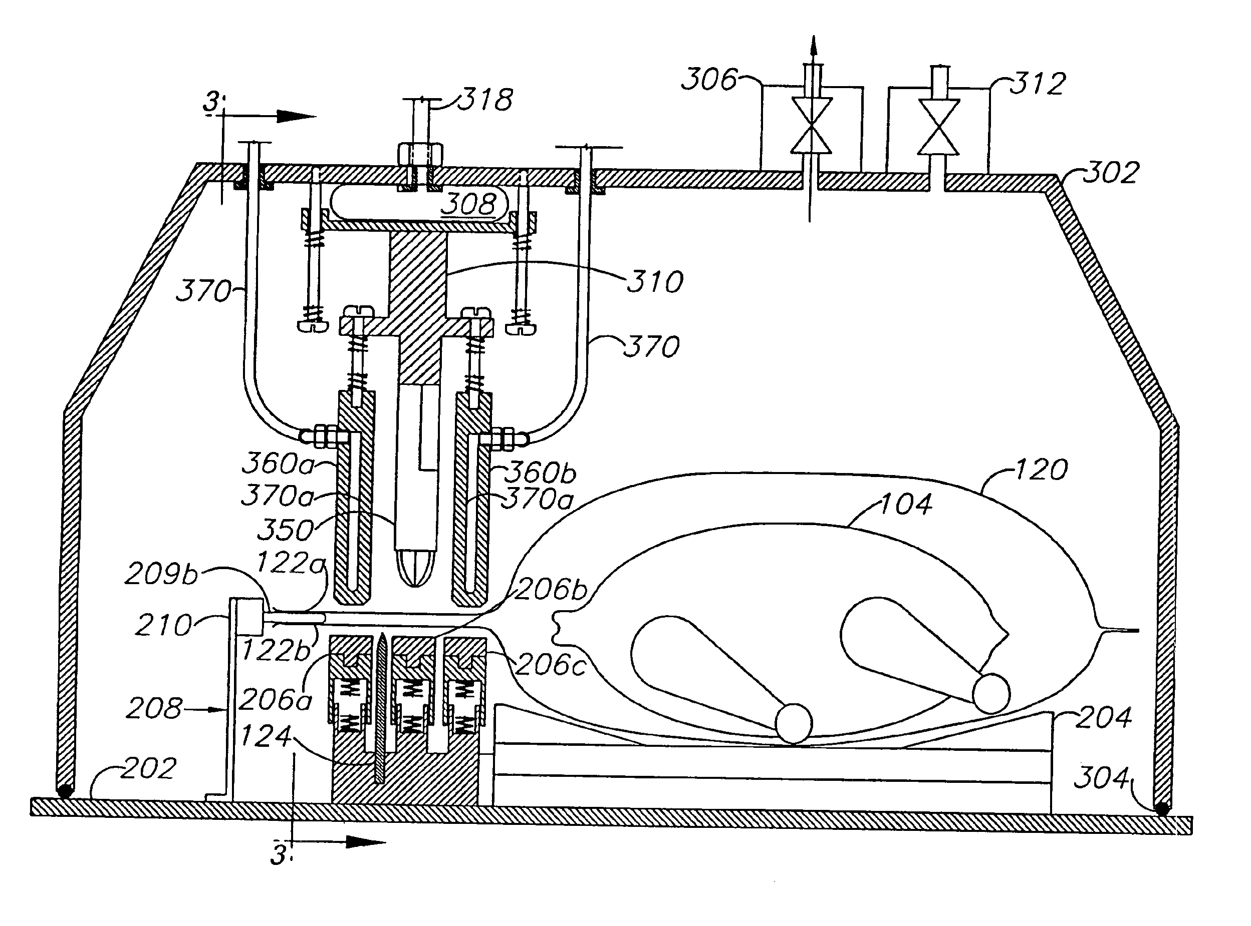
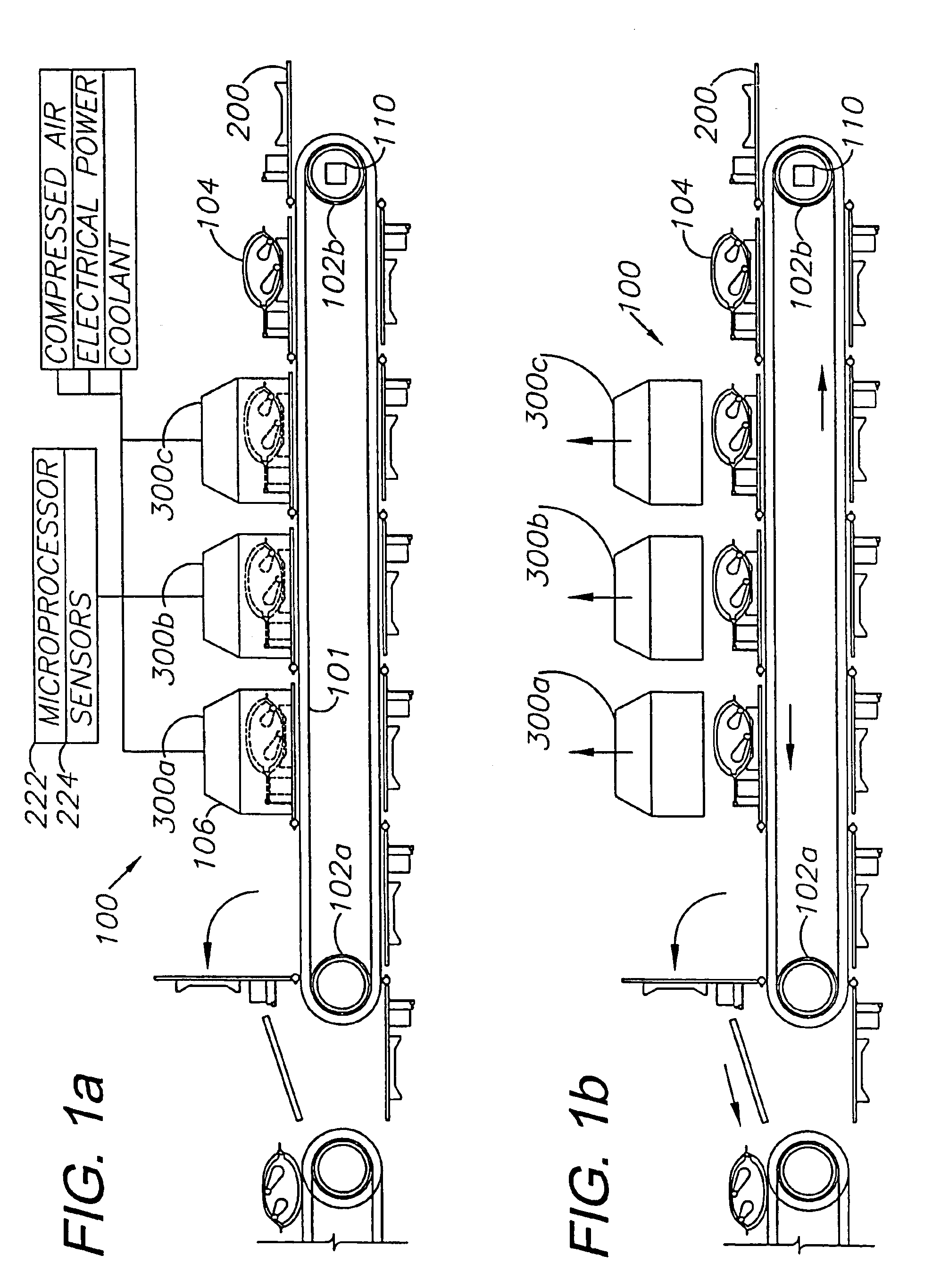
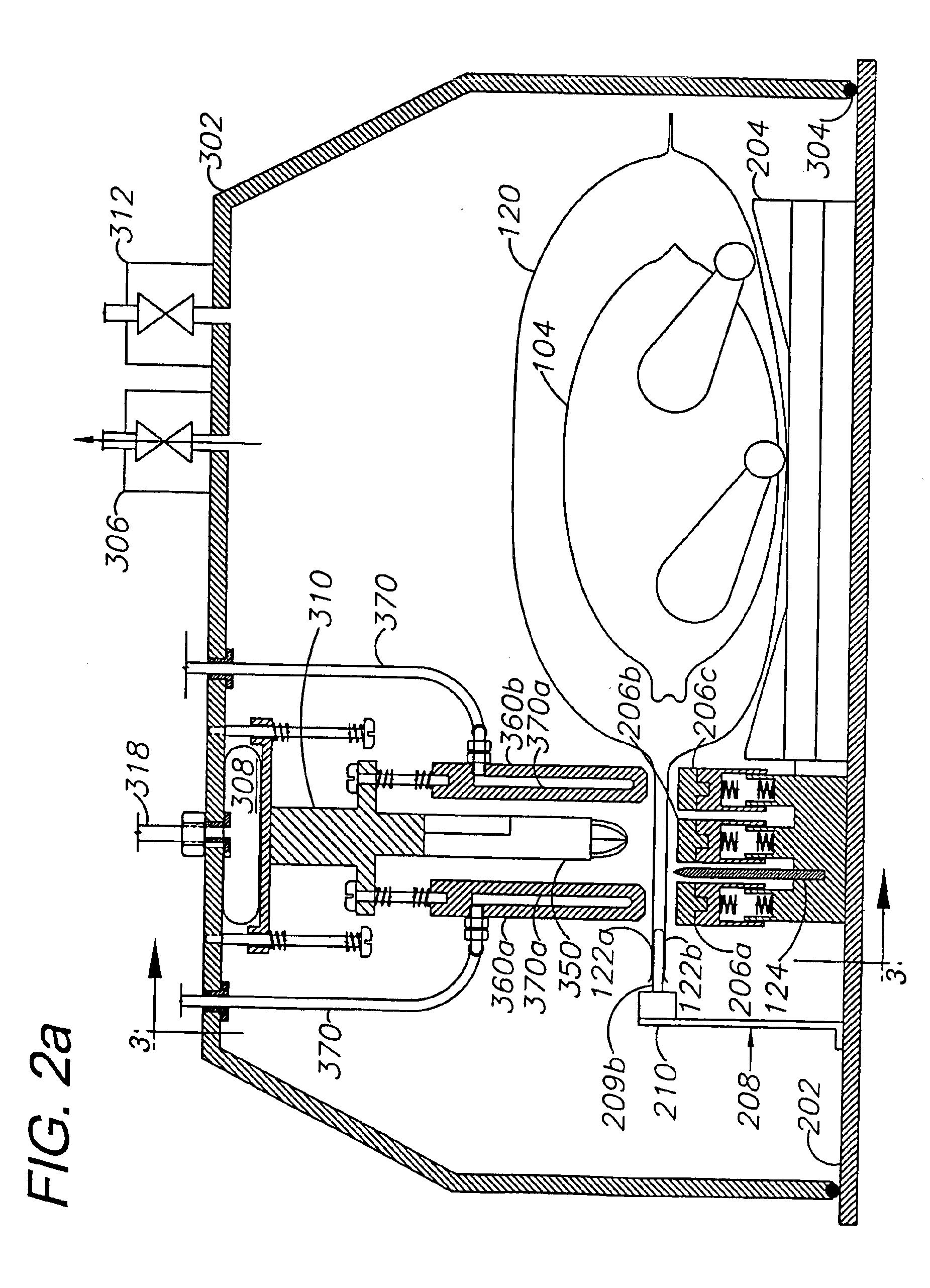
Turning to the figures, FIGS. 1a and 1b illustrate an automated multiple-chamber vacuum packaging machine 100. The machine includes a continuous, driven chain or belt 101 supported on and driven by an idler roller 102a and a drive roller 102b. As illustrated, a circuitous train of lower vacuum platens 200 are fastened at their leading edges to the belt 101. Preferably, the platens 200 are made of stainless steel. As illustrated in FIG. 1b, the platens are moving counterclockwise in a direction from right to left across the top. The belt 101 is driven by sprocket and bearing assemblies that are fixed to a drive shaft and a free wheeling shaft (not shown). The drive shaft is driven by a servo drive gear reduction motor 110. Three vacuum chambers 300 (individually denoted by numbers 300a, 300b and 300c) are mounted above the belt 101. The platens 200 and respective vacuum chambers 300 collectively form respective bag sealing units 106, which are capable of automated or semi-automated o...


PUM

PropertyMeasurementUnit
widthaaaaaaaaaa
electrical resistanceaaaaaaaaaa
vacuum chamberaaaaaaaaaa

Abstract

A system for sealing thermoplastic film includes one or more bag sealing units, each comprising a lower vacuum platen and a vacuum chamber cover adapted for sealing engagement on the platen to form a vacuum chamber. A sealing bar assembly includes a sealing bar designed for constant heated operation and a pair of cooling plates which function as heat sinks. The sealing bar assembly is pneumatically reciprocated between a raised, disengaged position and a lowered position with the sealing bar engaging the neck of a bag for hermetically sealing same. The cooling plates clamp the bag neck against a sealing support assembly. A method of sealing a thermoplastic film bag includes the steps of placing a packaging object in a thermoplastic bag and placing the bag on a cradle with the bag neck extending over a bag support assembly. A vacuum chamber cover is placed on the platen and evacuated to form a vacuum chamber. A sealing bar assembly melds the thermoplastic to form a sealed area across the bag neck. A cutoff knife blade severs the end of the bag beyond a sealed area, which extends across its neck.

Description

BACKGROUND OF THE INVENTIONThe present invention relates generally to vacuum packaging, and more particularly to an apparatus and system for thermally sealing bags using a constant temperature heat source located adjacent to one or more heat sinks.It is known in the prior art to seal perishable items, such as food products, by placing the item in a plastic bag, evacuating a substantial portion of the air within the bag to form a partial vacuum, and heat-sealing the bag opening to hermetically seal the bag and preserve the vacuum. Typically, this process is performed within a vacuum chamber. The bag containing the item or items to be packaged is placed into the chamber, and the chamber is closed. Air is evacuated from the chamber and the open end of the bag is sealed using a heat-sealing bar. As the bar comes into contact with the plastic, the plastic of both walls of the bag is melted, thereby causing the walls to meld or adhere to one another.Ordinarily, the vacuum chamber comprise...

Claims


Application Information

Patent Timeline
Patent Type & Authority Patents(United States)
IPC IPC(8): B65B31/02B29C65/00B29C65/18B29C65/74
CPCB29C65/18B29C65/745B29C65/7451B29C65/7461B29C65/7885B29C66/001B29C66/00145B29C66/1122B29C66/244B29C66/2442B29C66/348B29C66/43121B29C66/73921B29C66/80B29C66/81422B29C66/8161B29C66/81815B29C66/82421B29C66/8322B29C66/849B65B31/022B65B31/024B29C65/30B29C66/81811B29C65/305B29C65/00Y10T156/1084B29C66/91421B29C66/91431B29C66/91641B29C66/73715B29C66/8227
Inventor CADY, DERRIL R.TAYLOR, SR., MARK W.BALEK, THEODORE A.
Owner PACKTECH
Why Eureka
Try Eureka