Light bar with integrated warning illumination and lens support structure

a technology of warning light and lens support structure, which is applied in the direction of point-like light source, transportation and packaging, lighting and heating apparatus, etc., can solve the problems of lens portion binding during assembly, lens sliding relationship is difficult to seal against water penetration, and vehicle exposure to extreme heat and cold. , to achieve the effect of improving flexibility and efficiency of manufacture, improving weather resistance, and improving maintenance eas

Inactive Publication Date: 2005-03-08
WHELEN ENGINEERING COMPANY
View PDF13 Cites 46 Cited by
  • Summary
  • Abstract
  • Description
  • Claims
  • Application Information

AI Technical Summary

Benefits of technology

An object of the present invention is to provide a new and improved light bar for an emergency vehicle having improved weather resistance.
Another object of the present invention is to provide a new and improved light bar configuration having improved flexibility and efficiency of manufacture.
A further object of the present invention is to provide a new and improved light bar light bar for emergency vehicles having improved ease of maintenance.
A yet further object of the present invention is to provide a new and improved light bar for emergency vehicles wherein the useful life of the light bar may be extended by replacement of wear and sealing elements.

Problems solved by technology

While such a lens / support structure relationship allows for efficient and flexible manufacture, the sliding lens and channel relationship is difficult to seal against penetration by water.
Configuring the lens edges to be received more tightly in the locking grooves may cause the lens portions to bind during assembly.
Such vehicles are typically exposed to extremes of heat and cold as well as water in the form of ocean spray, rain, sleet, snow and ice.
Penetration of water or moisture into a light bar can have adverse effects ranging from fogging the lenses to corroding metal parts to destruction of electronic components.
Manufacture of a one-piece light-transmissive cover including clear and colored portions with different light refracting patterns is impractical.
A light bar with a light-transmissive cover assembled from discrete lens portions complicates the problem of providing a weather-resistant enclosure.
While this approach improves weather resistance of the junction between lens portions, it fails to address weather resistance of the joint between the longitudinally received lens portions and an extruded base.
The sliding relationship between the lens portions and the extruded base make inclusion of gasket or other sealing material in the joint problematic.
A further drawback to the light bar assembly typified by the '268 patent is that access to internal components in the middle of the light bar requires disassembly of all lens portions between one end of the light bar and the position of the component in need of service.
This approach lacks the flexibility of light bar fabrication provided by an elongated support structure with a light-transmissive cover that together define a substantially uninterrupted internal space.

Method used


Image

  • Light bar with integrated warning illumination and lens support structure
  • Light bar with integrated warning illumination and lens support structure
  • Light bar with integrated warning illumination and lens support structure

Examples


Embodiment Construction

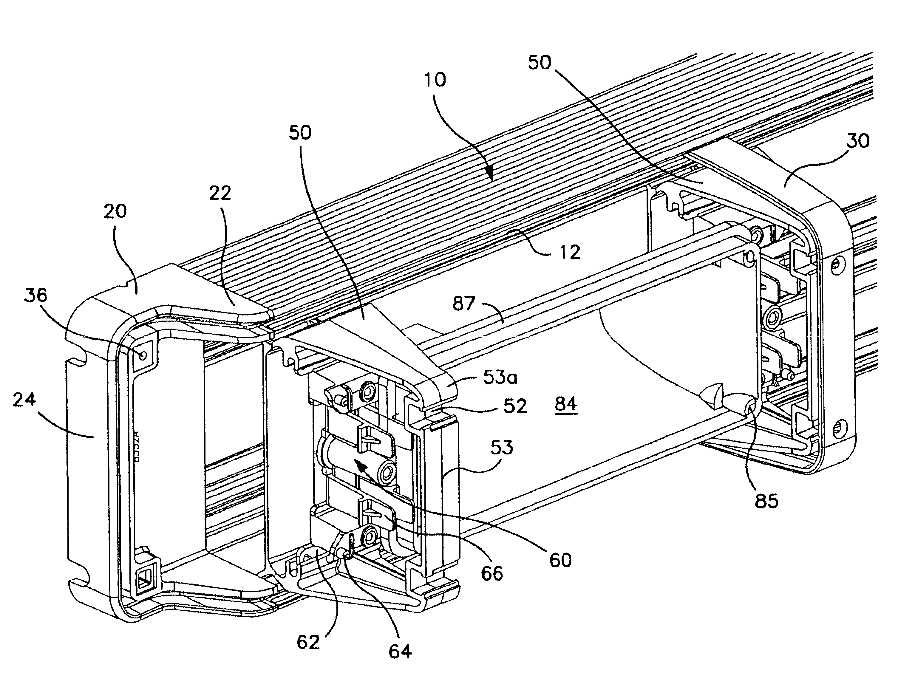
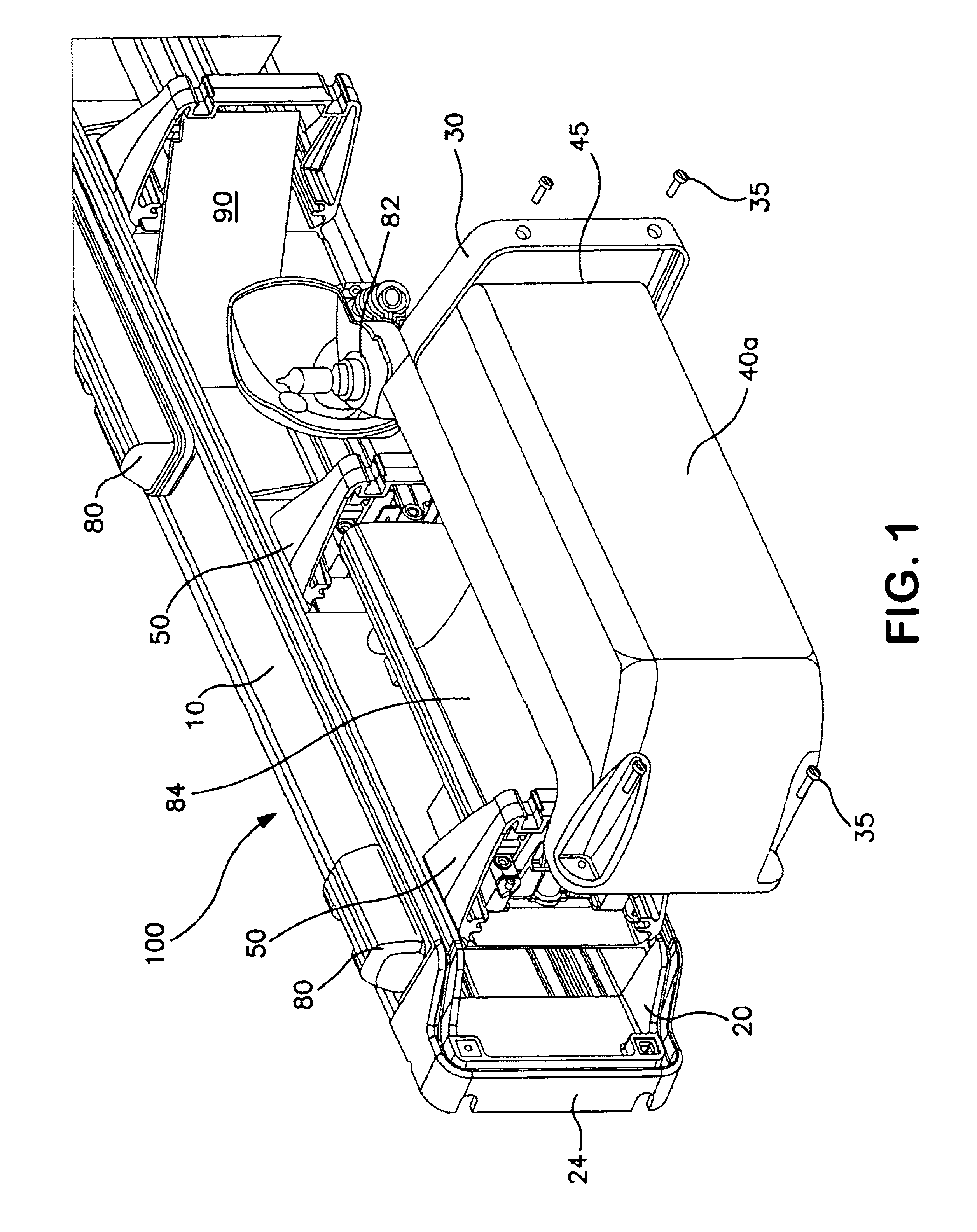
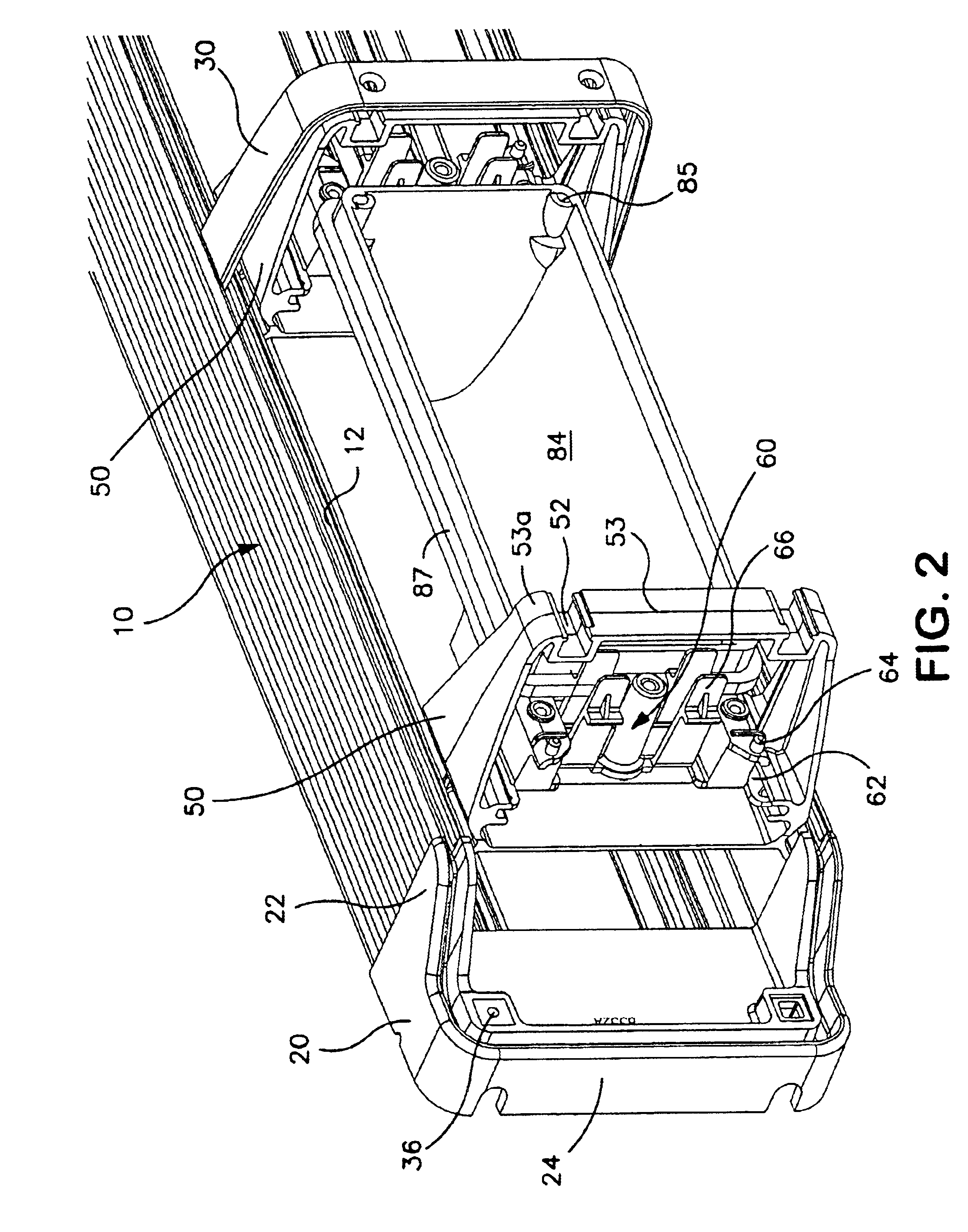
Exemplary light bars illustrating various aspects of the present invention will now be described with reference to FIGS. 1-8. The illustrated exemplary light bars 100 are configured for mounting on the forward (leading) or rear (trailing) upper edges of the utility body (not shown) on a vehicle such as an ambulance or fire truck. While various aspects of the invention will be described in the context of this exemplary light bar configuration, many aspects of the present invention are generally applicable to light bars, emergency signaling lights, traffic directors and other related assemblies.

FIGS. 1, 2 and 8 are left-end perspective views of exemplary alternative embodiments of a light bar 100 illustrating various aspects of the present invention. The components of a light bar 100 are mounted to a rigid base 10 of extruded aluminum. The configuration of the extruded base 10 is best shown in FIGS. 4-7. The base 10 has a generally uniform sectional configuration along its length. The...


PUM


Abstract

Brackets received in an elongated base support both lens portions and internal light bar components. Lens portion longitudinal edges penetrate the outer portion of a gasket channel to engage a gasket member. Lens retainer straps sandwich gasket layers to seal the longitudinal butt ends of lens portions. The lens retainers also penetrate the gasket channel to engage the gasket member. The brackets provide multiple locations for mounting warning light units and related light bar components within the space defined between the base and the lens portions.

Description

BACKGROUND OF THE INVENTION1. Field of the InventionThe present invention relates to warning light systems in the form of a light bar intended primarily for installation on land and marine vehicles and particularly to a light bar assembly having an integrated warning light and lens support structure.2. Description of the Related ArtWarning light assemblies in the form of light bars mounted on emergency vehicles are well known in the art. Such light bars typically comprise an elongated base to which warning lights and lenses are mounted. The light bar may also include power supplies and control circuitry to provide a self-contained light bar assembly. The light bar exterior typically includes multiple lenses that re-direct and / or color light from the warning light units mounted inside. A rigid base of metal or plastic provides mounting points for attaching the light bar to the emergency vehicle and for supporting the warning light units, lenses and other light bar components.It is kn...

Claims


Application Information

Patent Timeline
Patent Type & Authority Patents(United States)
IPC IPC(8): B60Q1/26
CPCB60Q1/2611
Inventor SMITH, KEVIN M.
Owner WHELEN ENGINEERING COMPANY
Why Eureka
Try Eureka