X-ray source employing a compact electron beam accelerator

a technology of electron beam and accelerator, which is applied in the direction of accelerator, klystron, electric discharge tube, etc., can solve the problems of reducing the electron current reaching the x-ray target, generating undesirable leakage x-ray radiation, etc., and achieves the effect of maximizing beam energy and minimizing leakage x-ray radiation

Inactive Publication Date: 2005-03-08
VARIAN MEDICAL SYSTEMS
View PDF15 Cites 41 Cited by
  • Summary
  • Abstract
  • Description
  • Claims
  • Application Information

AI Technical Summary

Benefits of technology

It is a general object of an invention to provide a compact linear accelerator in which the beam energy is maximized and leakage x-ray radiation is minimized.
It is still another object of the present invention to provide a compact linear accelerator which is simple in design and easy to manufacture.

Problems solved by technology

Electrons which strike cavity walls during their travel through the accelerator not only reduce the electron current reaching the x-ray target but also generate undesirable leakage x-ray radiation.

Method used


Image

  • X-ray source employing a compact electron beam accelerator
  • X-ray source employing a compact electron beam accelerator
  • X-ray source employing a compact electron beam accelerator

Examples


Embodiment Construction

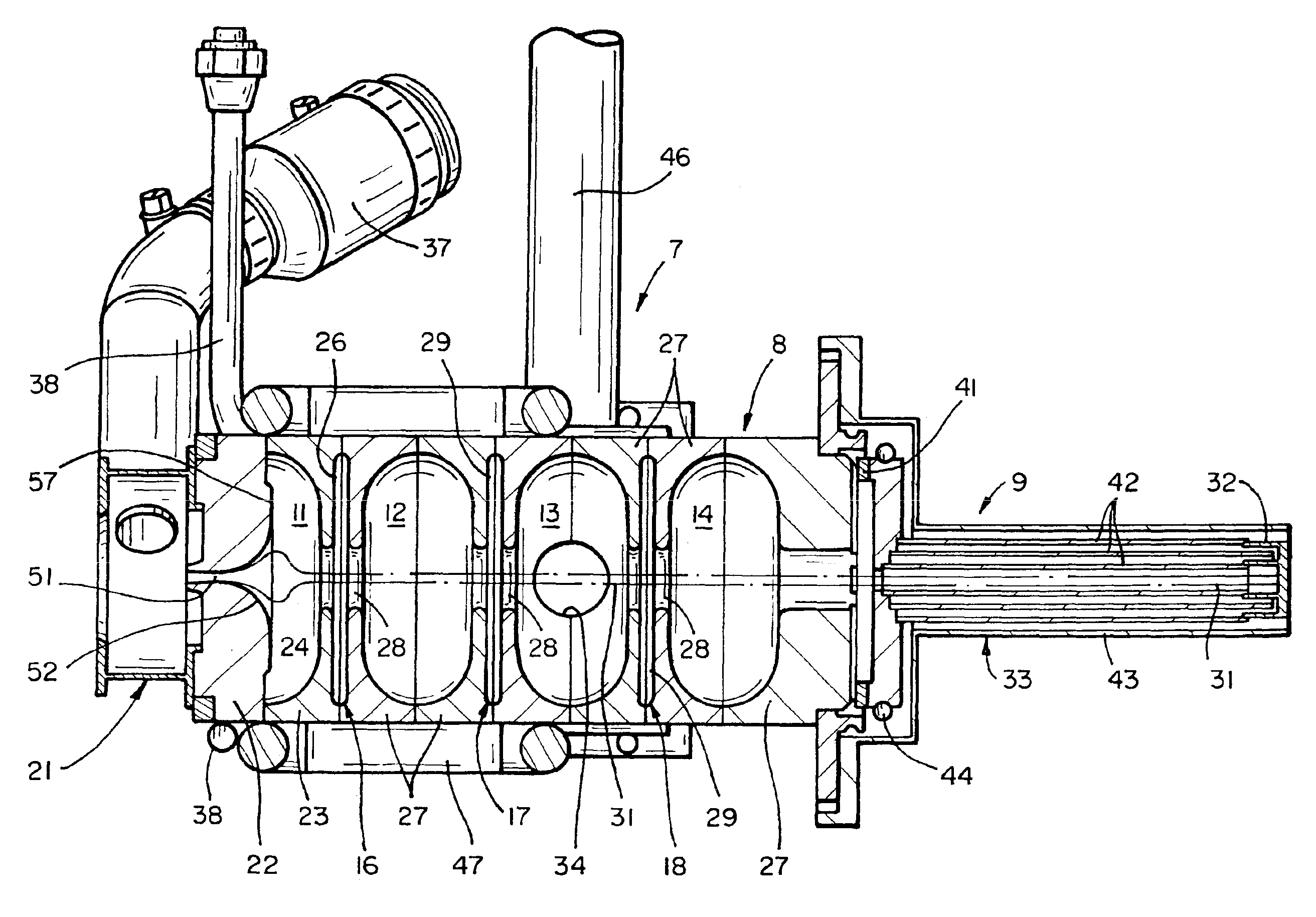
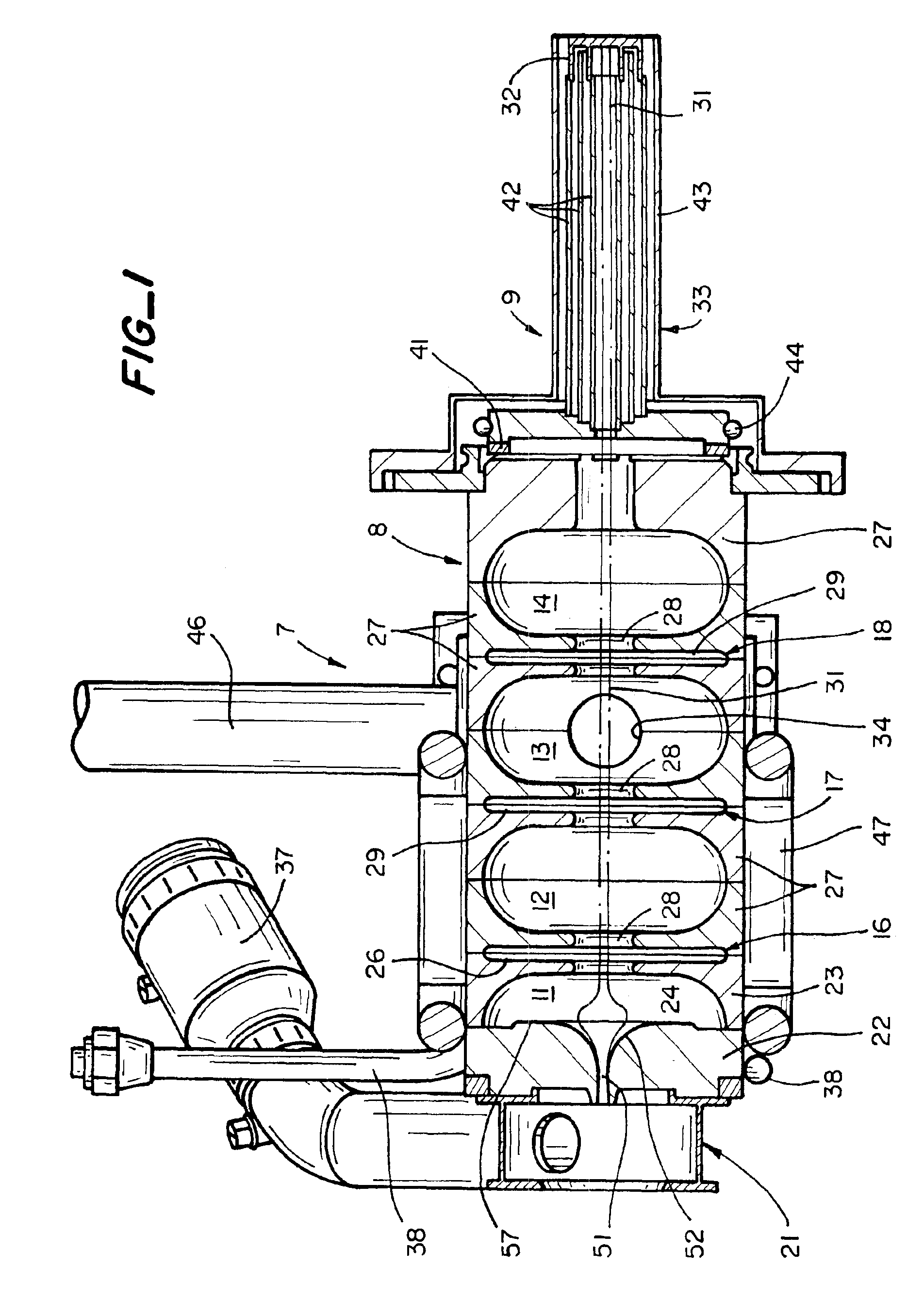
FIG. 1 is an axial sectional view of an x-ray source 7 including a standing wave electron beam accelerator structure 8 and extended target 9 in accordance with one embodiment of the present invention. It comprises a chain of electrically coupled resonant cells or cavities. The cells comprise a buncher cell 11 and in-line resonant cells 12, 13 and 14. The cells are electrically coupled by on-axis coupling cells 16, 17 and 18 formed by joining facing half-cells. Electrons are injected into the buncher cell 11 by an electron gun 21, which includes an anode plate 22 that forms one wall of the buncher cell 11. The other walls of the buncher cell are formed by the cup-shaped half-cell 23 which includes an iris or opening 24. The half cell includes an outer recessed region 26. Each of the remaining cells 12, 13 and 14 are formed by identical cup shaped half cells 27 which include beam tunnel irises or openings 28 and outer recesses 29. When the half-cell 23 and anode plate 22 are joined to...


PUM


Abstract

A standing wave electron beam accelerator and x-ray source is described. The accelerator has a plurality of on-axis resonant cells having axial apertures electrically coupled to one another by on-axis coupling cells having axial apertures. The accelerator includes a buncher cavity defined in part by an apertured anode and a half cell. The buncher cavity is configured to receive electrons injected through said anode aperture and r.f. focus them into a beam which is projected along the axis through said apertures. An x-ray target is supported in spaced relationship to said accelerator by a support having a smaller diameter than the accelerator.

Description

BRIEF DESCRIPTION OF THE INVENTIONThis invention relates generally to x-ray sources employing standing wave electron beam accelerators, and more particularly x-ray sources employing compact high-energy electron beam accelerators having low-leakage x-ray radiation to minimize shielding requirement.BACKGROUND OF THE INVENTIONStanding wave type linear accelerators generate high-energy electron beams which strike metallic targets to generate x-rays. The linear accelerators have a series of linearly arranged cavity resonators separated by apertured walls. The apertures define a passage through which the electron beam travels to interact with standing waves supported in the cavities. The beam gains energy as it travels through successive resonant cavities. The electrons are injected into the first cavity at relatively low energy by an electron gun. The electron beam is accelerated as it travels through the cavities. Electrons which strike cavity walls during their travel through the accel...

Claims


Application Information

Patent Timeline
Patent Type & Authority Patents(United States)
IPC IPC(8): H01J35/00H05H9/00H05H9/04
CPCH05H9/04H01J35/00
Inventor TRAIL, MARK E.WHITTUM, DAVID H.MEDDAUGH, GARD E.
Owner VARIAN MEDICAL SYSTEMS
Why Eureka
Try Eureka