Cascode distributed amplifier

a distributed amplifier and cascode technology, applied in the field of semiconductor circuits, can solve the problems of increasing the possibility of receiving error for the input signal, the voltage gain of the output signal to the input signal is rapidly increased, and the cascode distributed amplifier deteriorates, so as to prevent the rapid increase of negative polarity resistance and stable amplifying operation

Inactive Publication Date: 2005-03-08
FUJITSU LTD
View PDF6 Cites 43 Cited by
  • Summary
  • Abstract
  • Description
  • Claims
  • Application Information

AI Technical Summary

Benefits of technology

In the cascode distributed amplifier of the present invention, the damping resistor is provided in each of the unit circuits and it prevents the rapid increase of the negative-polarity resistance in the high frequency range. By using the negative-polarity resistance, the cascode distributed amplifier provides stable amplifying operation even when the frequency of the input signal is in the high frequency range. Moreover, the variable capacitor having a variable capacitance is provided in each of the unit circuits. By changing a control voltage applied to the variable capacitor, the cascode distributed amplifier of the present invention compensates for variations of the frequency characteristics of a subsequently connected circuit.

Problems solved by technology

However, the conventional cascode distributed amplifier has the following problems.
In other words, the negative-polarity resistance of the conventional cascode distributed amplifier is rapidly increased in the vicinity of the cut-off frequency, and the oscillation of the cascode distributed amplifier occurs at such frequency, which results in a rapid increase of the voltage gain of the output signal to the input signal.
When the peaking of the voltage gain occurs, the eye pattern of the conventional cascode distributed amplifier deteriorates, and the possibility of a receiving error for the input signal is increased.
Further, in the conventional cascode distributed amplifier in FIG. 1, variations of the frequency characteristics of a subsequently connected circuit (for example, an LN modulator) due to changes of the manufacturing conditions thereof are not taken into consideration.
If the frequency characteristics of the driver circuit for the LN modulator and the frequency characteristics of the LN modulator are not fitted to each other, each of the high level and the low level of the eye pattern has a certain width, and the error ratio of the signal transmitted by the transmission system is increased.

Method used


Image

  • Cascode distributed amplifier
  • Cascode distributed amplifier
  • Cascode distributed amplifier

Examples


Embodiment Construction

A description will now be provided of the preferred embodiments of the present invention with reference to the accompanying drawings.

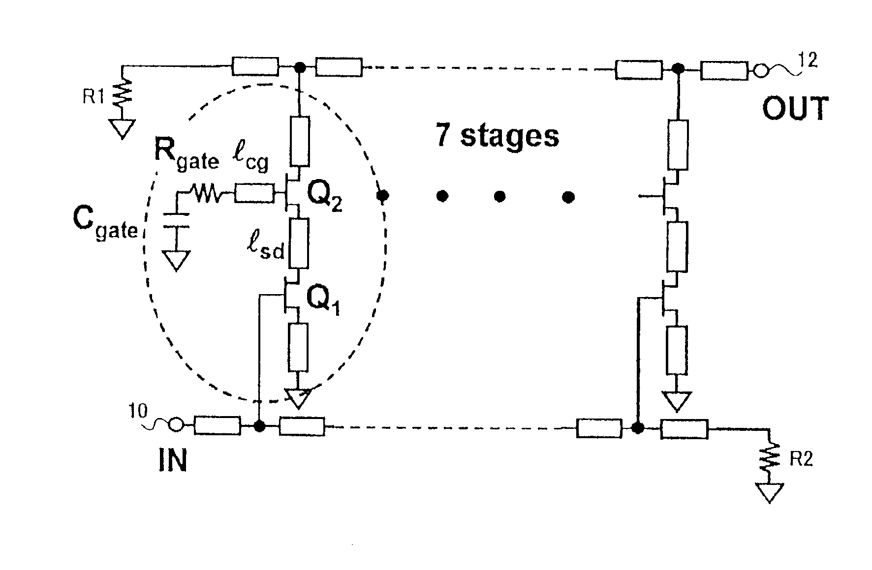
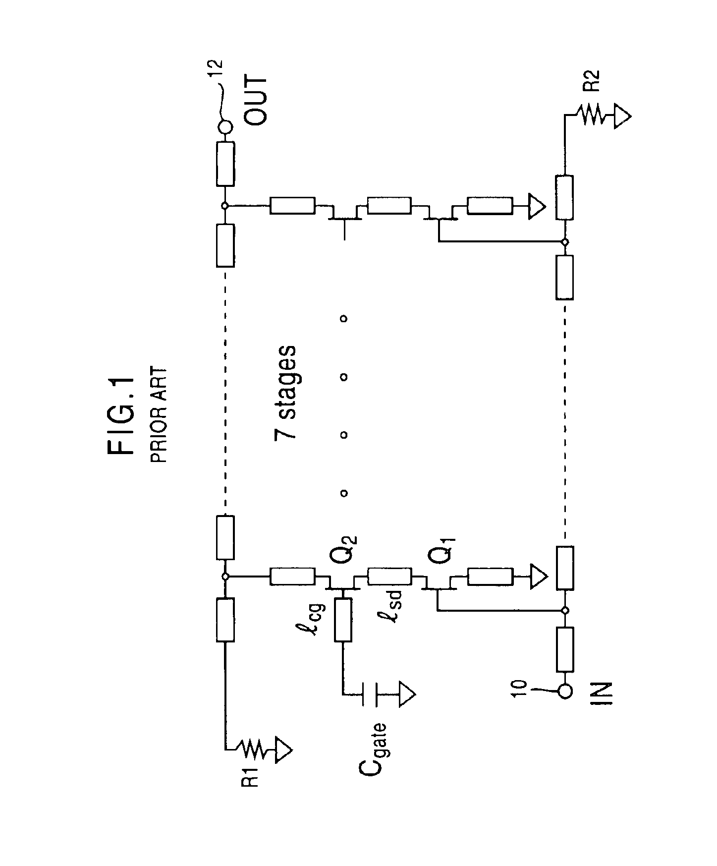
FIG. 3 shows a single-phase cascode distributed amplifier according to a first preferred embodiment of the invention. In FIG. 3, the elements that are essentially the same as corresponding elements in FIG. 1 are designated by the same reference numerals.

As shown in FIG. 3, the cascode distributed amplifier of the present embodiment is constructed by the plurality of unit circuits (in the example of FIG. 3, seven unit circuits), each including the first transistor Q1 and the second transistor Q2, and the plurality of unit circuits are connected in parallel. An input signal IN is supplied to the input terminal 10 at one end of the input-side transmission wire, and an amplified signal OUT generated by the distributed amplifier is supplied from the output terminal 12 at one end of the output-side transmission wire.

In FIG. 3, the resistor R1 is a terminatio...


PUM


Abstract

In a cascode distributed amplifier of the present invention, a plurality of unit circuits are connected in parallel, and each unit circuit includes a pair of first and second transistors connected in series between an input transmission wire and an output transmission wire. The first transistor has a gate connected to the input transmission wire, a source grounded and a drain connected to the second transistor. The second transistor has a gate grounded, a source connected to the drain of the first transistor and a drain connected to the output transmission wire. Each unit circuit includes a damping resistor having a first end connected to the gate of the second transistor and a second end, and a capacitor having a first end connected to the second end of the damping resistor and a second end grounded.

Description

BACKGROUND OF THE INVENTION1. Field of the InventionThe present invention relates to semiconductor circuits including transistors such as bipolar transistors or field-effect transistors. More specifically, the present invention relates to a cascode distributed amplifier in which a plurality of unit circuits, each including a grounded-gate transistor, are connected in parallel.Recently, with the widespread proliferation of the Internet, the demand for a broadband transmission system capable of transmitting and receiving a large quantity of data at a high bit rate of 40 G b / s has increased. For this reason, there is also the demand for a broadband amplifier with a high frequency band of 40 GHz or above, which is one component of the broadband transmission system of the above type. In a transmitter of the broadband transmission system, a driver circuit is disposed at the front end the transmitter to drive a LN (lithium niobate) modulator. To obtain a high output voltage Vpp, ranging fr...

Claims


Application Information

Patent Timeline
Patent Type & Authority Patents(United States)
IPC IPC(8): H03F1/08H03F3/60H03F1/22
CPCH03F3/607H03F1/223
Inventor SHIGEMATSU, HISAO
Owner FUJITSU LTD
Why Eureka
Try Eureka