Optical member and liquid-crystal display device

a liquid crystal display and optical member technology, applied in the field of optical members, can solve the problems of lowering contrast and similar problems when using linear polarizers, and achieve the effects of excellent visibility, and preventing the reduction of contrast in a pixel division display method

Inactive Publication Date: 2005-03-08
NITTO DENKO CORP
View PDF8 Cites 39 Cited by
  • Summary
  • Abstract
  • Description
  • Claims
  • Application Information

AI Technical Summary

Benefits of technology

An object of the invention is to develop an optical member which prevents reduction in contrast in a pixel division display method by use of a polarizer to thereby make it possible to form a liquid-crystal display device excellent in visibility such as contrast or brightness at a wide viewing angle. Another object of the inven...

Problems solved by technology

There was however a problem that contrast was lowered because light leakage occu...

Method used


Image

  • Optical member and liquid-crystal display device
  • Optical member and liquid-crystal display device

Examples


example 1

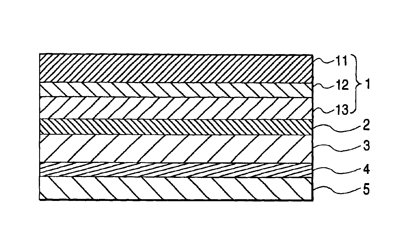
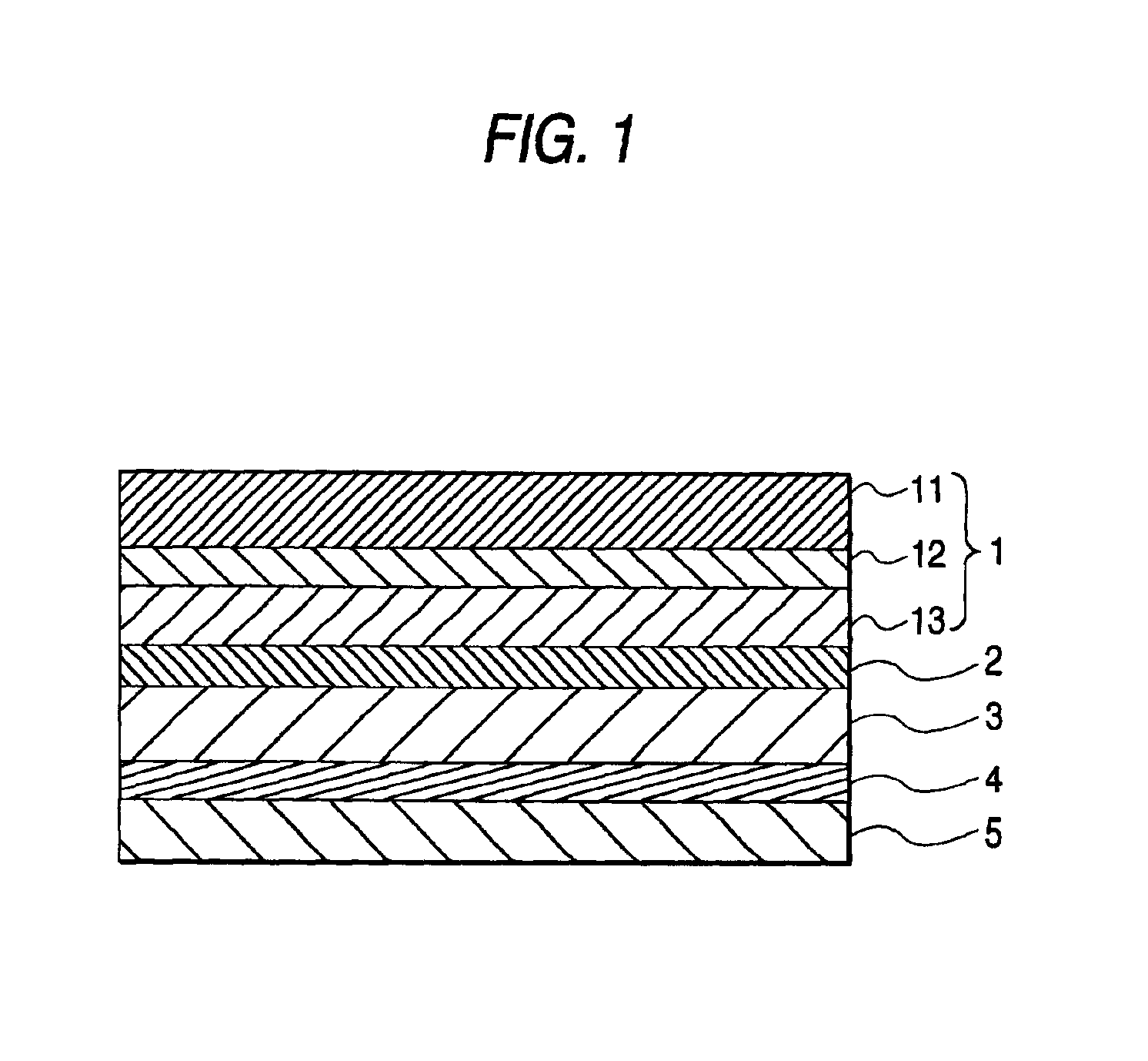
Opposite surfaces of a polarizing film made of iodine-adsorbed polyvinyl alcohol were bonded to and protected by cellulose triacetate films each having a refractive index (ND20, which will apply hereunder) of 1.485 to thereby form a linearly polarizer (single transmittance: 43%, the degree of polarization: 99.5%). A quarter-wave plate (frontal retardation: 140 nm at light with a wavelength of 550 nm, which will apply hereunder) constituted by a uniaxially drawn film of a norbornene resin with a refractive index of 1.513 was bonded and laminated onto one surface of the linearly polarizer through an adhesive layer with a refractive index of 1.506 to thereby obtain a circularly polarizer. A viewing angle compensating plate (frontal retardation: 0 nm, thicknesswise retardation: 100 nm) constituted by a biaxially drawn film of the same norbornene resin as described above was bonded and laminated onto the quarter-wave plate side of the circularly polarizer through an adhesive layer the sa...

example 2

Four kinds of cholesteric liquid-crystal polymer layers mirror-reflecting right-handed circularly polarized light in wavelength ranges of (A) from 650 to 750 nm, (B) from 550 to 650 nm, (C) from 450 to 550 nm and (D) from 350 to 450 nm respectively were obtained by the following method. A 0.1 μm-thick polyvinyl alcohol layer was provided on a 50 μm-thick cellulose triacetate film (refractive index: 1.485) exhibiting no birefringence and rubbed with rayon cloth to thereby form an oriented film. On the oriented film, 20% by weight of a tetrahydrofuran solution of an acrylic thermotropic cholesteric liquid-crystal polymer was applied by a wire bar and dried. Then, the solution was heated at 150° C. for 5 minutes so as to be oriented and then left at room temperature so as to be cooled. Thus, a 1.5 m-thick cholesteric liquid-crystal polymer layer oriented in Grandjean texture was formed.

Then, the cholesteric liquid-crystal polymer layers (A) and (B) were thermal-compression bonded to ea...


PUM


Abstract

An optical member has a polarizer, a viewing angle compensating plate, and an adhesive layer which has a refractive index ND20 not lower than 1.485 and through which the polarizer and the viewing angle compensating plate are laminated on each other. A liquid-crystal display device has at least one optical member defined above, a liquid-crystal cell, and an adhesive layer which has a refractive index ND20 not lower than 1.485 and through which the optical member is bonded onto at least one of opposite surfaces of the liquid-crystal cell.

Description

BACKGROUND OF THE INVENTION1. Field of the InventionThe present invention relates to an optical member capable of being used for forming a liquid-crystal display device excellent in visibility such as contrast or brightness at a wide viewing angle.2. Description of the Related ArtHigh contrast of 10 or higher in a viewing angle range of 80 degrees in vertical and horizontal directions has been heretofore required of a large-screen TV, or the like, using liquid-crystal display. In consideration of this requirement, a method using a circularly polarizer to solve a problem of reduction in luminance due to reduction in numerical aperture on the basis of split portions obtained by dividing each pixel into multiple domains compared with a mono-domain type has been proposed (Proceedings of SID2000 [31, 35.3(2000)902]) in a liquid-crystal panel of the type in which orientation of liquid crystal is divided into fine domains as in a multiple-domain VA (vertical alignment) mode to compensate f...

Claims


Application Information

Patent Timeline
IPC IPC(8): G02F1/13G02F1/13363
CPCG02B5/3083G02F1/13363G02F2001/133638G02F2001/133633G02F1/133633G02F1/133638
Inventor MIYATAKE, MINORUYANO, SHUUJINISHIKOUJI, YUUICHI
Owner NITTO DENKO CORP
Why Eureka
Try Eureka