Adaptive asymmetric network connectivity probing system and method

a network connectivity and asymmetric technology, applied in the field of improved data transfer, can solve the problems of inability to adapt to other data protocols or be expanded to monitor other service level performance metrics, cannot allow both nodes to measure the round trip delay of the same sequence of cells, and cannot individually determine the round trip delay of the probe. the effect of improving data transfer in the communications network

Inactive Publication Date: 2005-03-08
SIEMENS PROD LIFECYCLE MANAGEMENT SOFTWARE INC
View PDF4 Cites 7 Cited by
  • Summary
  • Abstract
  • Description
  • Claims
  • Application Information

AI Technical Summary

Benefits of technology

To address the above-discussed deficiencies of the prior art, it is a primary object o

Problems solved by technology

That is, the passive probes cannot individually determine round trip delay, and each probe must store and transmit a substantial amount of data to the console which is required to correlate signature and timestamp data from different sites.
Because the technique relies, in part, on timestamps already present in PM OAM (performance management operations, administration and maintenance) ATM cells, the technique is specific to the ATM protocol and cannot readily be adapted to other data protocols or be expanded to monitor other service level performance metrics.
Further, the technique does not allow both nodes to measure the round trip delay of the same sequence of cells (i.e., either only one of the two nodes measures round trip delay or the two node measure delays of different transmitted cell sequences).
Further, while it is possible for individual switches in existing network systems to indicate how many packets of data have been dropped by the switch, there are no known systems capable of measuring a rate of successful (or unsuccessful) data delivery on a service level, e.g., over a particular virtual circuit or to a particular end user.
The problem of providing service level analysis of network performance is complicated by the fact that many switching networks comprise interworked systems using plural, diffe

Method used


Image

  • Adaptive asymmetric network connectivity probing system and method
  • Adaptive asymmetric network connectivity probing system and method
  • Adaptive asymmetric network connectivity probing system and method

Examples


Embodiment Construction

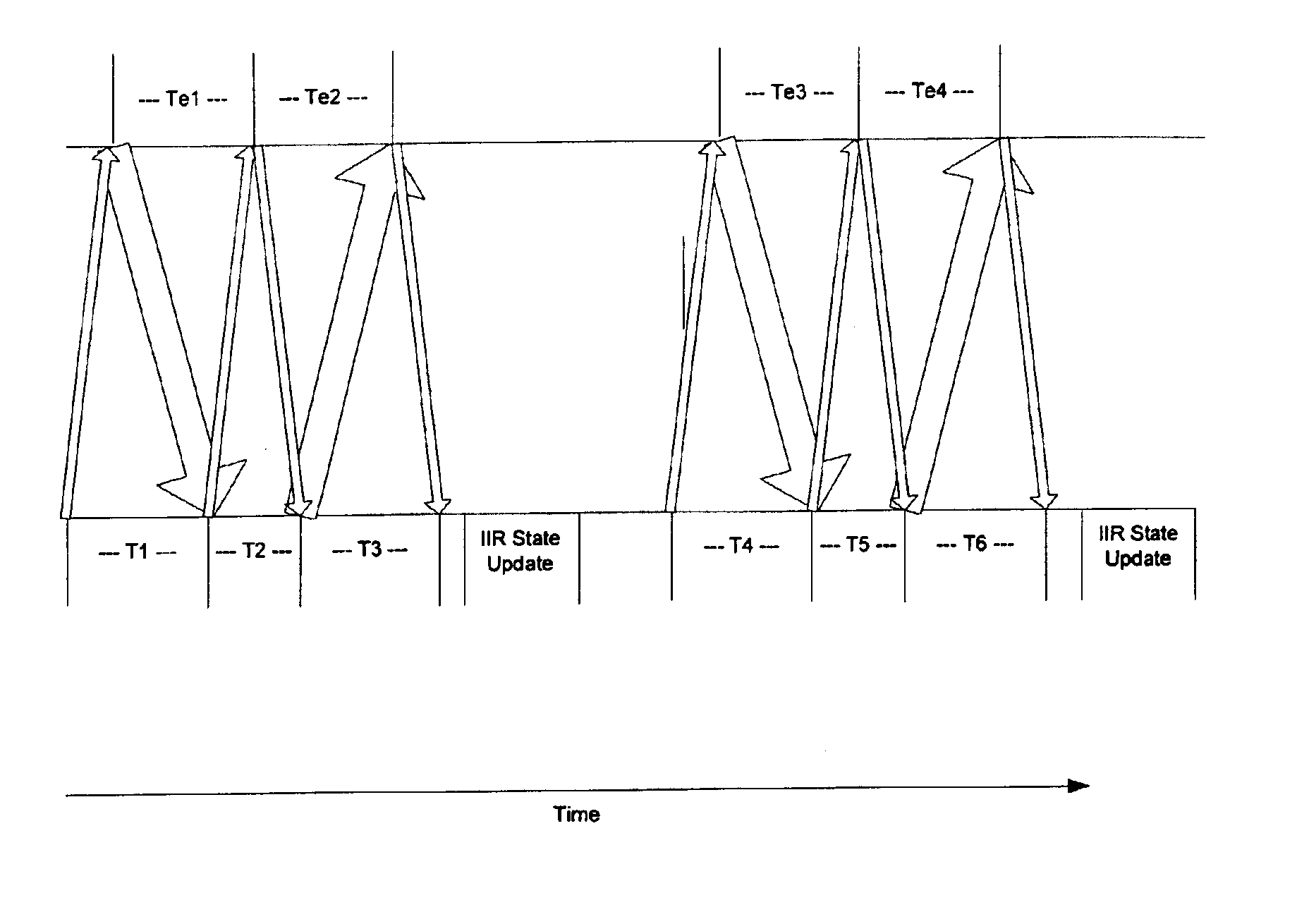
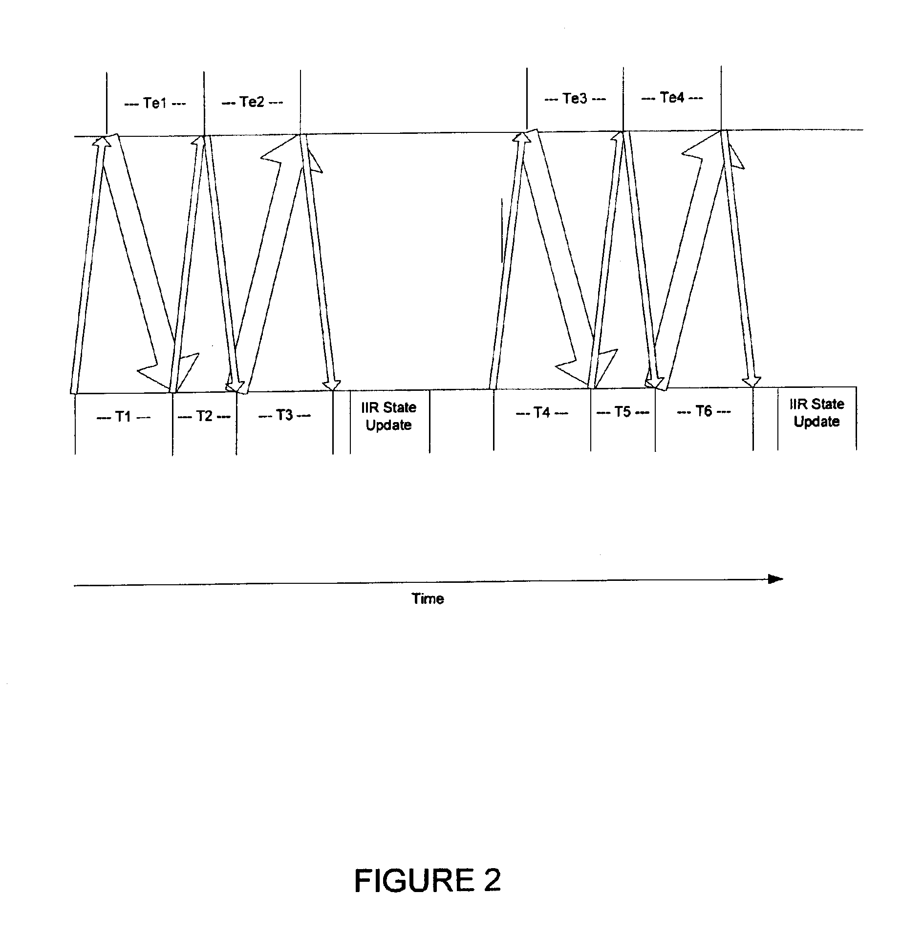
FIGS. 1 through 4, discussed below, and the various embodiments used to describe the principles of the present invention in this patent document are by way of illustration only and should not be construed in any way to limit the scope of the invention. Those skilled in the art will understand that the principles of the present invention may be implemented in any suitably arranged device. The numerous innovative teachings of the present application will be described with particular reference to the presently preferred embodiment.

Definitions: Following are short definitions of the usual meanings of some of the technical terms which are used in the present application. (However, those of ordinary skill will recognize whether the context requires a different meaning.) Additional definitions can be found in the standard technical dictionaries and journals.

latency: The round-trip-delay (RTD) of a network connection for a message of minimum possible size for the connection protocol.

BW: Ban...


PUM


Abstract

A system and method for analyzing network traffic between a client system and multiple mirror systems, to determine the most efficient data transfer paths for accessing the mirrored data. Accordingly, a set of network probes are passed between network point pairs. After doing so, the resulting figures are analyzed using a first-order linear equation to determine which pairs are “closest” in terms of data transfer efficiency in a specific direction. Using the closeness results, the optimal data paths for large data transfer are determined.

Description

TECHNICAL FIELD OF THE INVENTIONThe present invention is directed, in general, to improved data transfer in a communications network and, more specifically, to a system and method for determining and selecting the most efficient path for a data transfer.BACKGROUND OF THE INVENTIONDue to an increasing reliance on large-volume data transfers, there is an increasing need to accurately measure operational performance of data communications networks. Communications networks, especially packetized data networks, are currently utilized in various applications for transmission and reception of data between parties at different locations. A typical data transmission system includes a plurality of end user sites and a data packet switching network, which resides between the sites to facilitate communications. Each site is connected to the switching network via an access channel (i.e., a channel connecting a site to a communications system), wherein transmission circuits, preferably virtual ci...

Claims


Application Information

Patent Timeline
IPC IPC(8): H04L12/56H04L12/24H04L12/26H04L29/06H04L29/08
CPCH04L12/2697H04L41/5009H04L43/0864H04L43/0882H04L43/12H04L67/1023H04L45/26H04L67/101H04L43/50H04L2029/06054H04L67/1008H04L67/1002H04L67/10015H04L67/1001
Inventor ENGBRECHT, MICHAEL R.
Owner SIEMENS PROD LIFECYCLE MANAGEMENT SOFTWARE INC
Why Eureka
Try Eureka