Multitasking processor system for monitoring interrupt events

Inactive Publication Date: 2005-03-08
INFINEON TECH AG
View PDF7 Cites 31 Cited by
  • Summary
  • Abstract
  • Description
  • Claims
  • Application Information

AI Technical Summary

Benefits of technology

[0009]The present invention is, therefore, based on the object of proposing a processor system with interrupt proc

Problems solved by technology

It is only events having this particular pri

Method used


Image

  • Multitasking processor system for monitoring interrupt events
  • Multitasking processor system for monitoring interrupt events
  • Multitasking processor system for monitoring interrupt events

Examples


Embodiment Construction

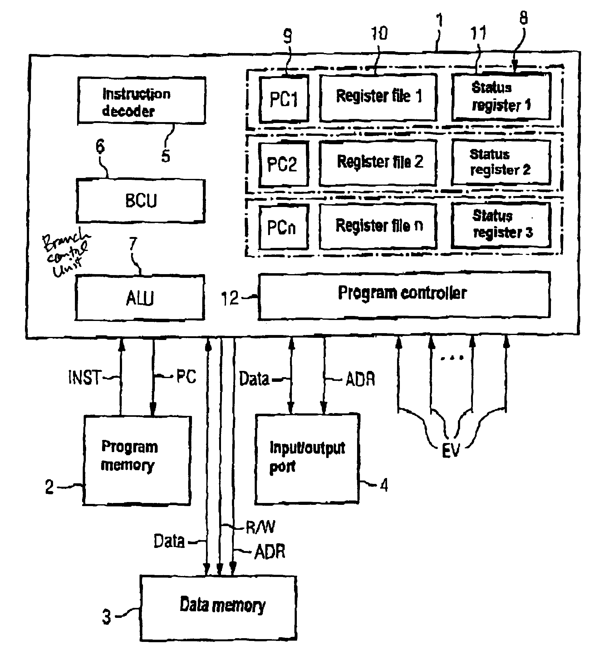
[0019]The processor system shown in FIG. 1 comprises a processor unit 1 which comprises, among other things, a program controller 12 and an instruction decoder 5, a so-called branch control unit (BCU) 6 and at least one arithmetic logic unit (ALU) 7. In addition, an individual or task-specific hardware environment 8 is provided for each task which can be executed on the processor system and which in each case comprises a memory stack 9, a register bank with one or more registers 10 and one or more status registers 11. In the memory stack 9, the instantaneous value of the program counter (PC) of the corresponding task is stored in each case. The registers 10 are used for temporarily storing data during the processing of the corresponding task. The status registers 11, on the other hand, are intended for storing status information or status flags such as, for example, zero or carry flags so that the content of the status registers in each case designates the current status of the corr...


PUM


Abstract

In a processor system, different memory means (8), which can in each case comprise a memory stack (9) for the instruction counter, a register (10) for temporarily storing data and status register (11), are provided for various tasks. When an interrupt event (EV) occurs which causes a change from a current task to a new task, a controller (21) switches from the memory means (8) allocated to the old task to the memory means (8) allocated to the new task.

Description

DESCRIPTION[0002]1. Technical Field[0003]The present invention relates to a processor system according to the precharecterizing clause of claim 1, which is pro interrupts.[0004]2. Background Art[0005]Telecommunication terminals such as, for example, modems or so-called line cards must be able to respond to particular software or hardware events. If a processor system is used for control purposes in such telecommunication terminals, interrupt processing is usually provided in the processor system so that it can respond to the events described above.[0006]For the interrupt processing, the individual events which can trigger an interrupt in the processor system are monitored. As soon as the occurrence of an interrupt event has been detected, a corresponding interrupt request signal is generated and transmitted to a processor unit of the processor system which thereupon determines the start address of the corresponding interrupt routine which is supposed to run for executing the interru...

Claims


Application Information

Patent Timeline
IPC IPC(8): G06F9/38G06F9/42G06F9/46G06F9/48
CPCG06F9/3851G06F9/4881G06F9/46
Inventor HOBER, PETERJENKNER, CHRISTIANNIE, XIAONING
Owner INFINEON TECH AG
Why Eureka
Try Eureka