Method for making a well perforating gun

a perforating gun and perforating technology, applied in the direction of manufacturing tools, explosive charges, borehole/well accessories, etc., can solve the problems of affecting the quality of the gun, the cost of materials, and the jamming of the casing

Inactive Publication Date: 2005-03-15
KASH EDWARD CANNOY
View PDF13 Cites 28 Cited by
  • Summary
  • Abstract
  • Description
  • Claims
  • Application Information

AI Technical Summary

Problems solved by technology

A gun must allow explosions to penetrate the gun body, but not allow the tubing to split or otherwise lose its original shape Extreme distortion of the gun may cause it to jam within the casing.
Although effective, guns are relatively expensive.
Most of the expense involved in manufacturing guns is the cost of material.
Unfortunately, these efforts have seen only limited success.

Method used


Image

  • Method for making a well perforating gun
  • Method for making a well perforating gun
  • Method for making a well perforating gun

Examples


Embodiment Construction

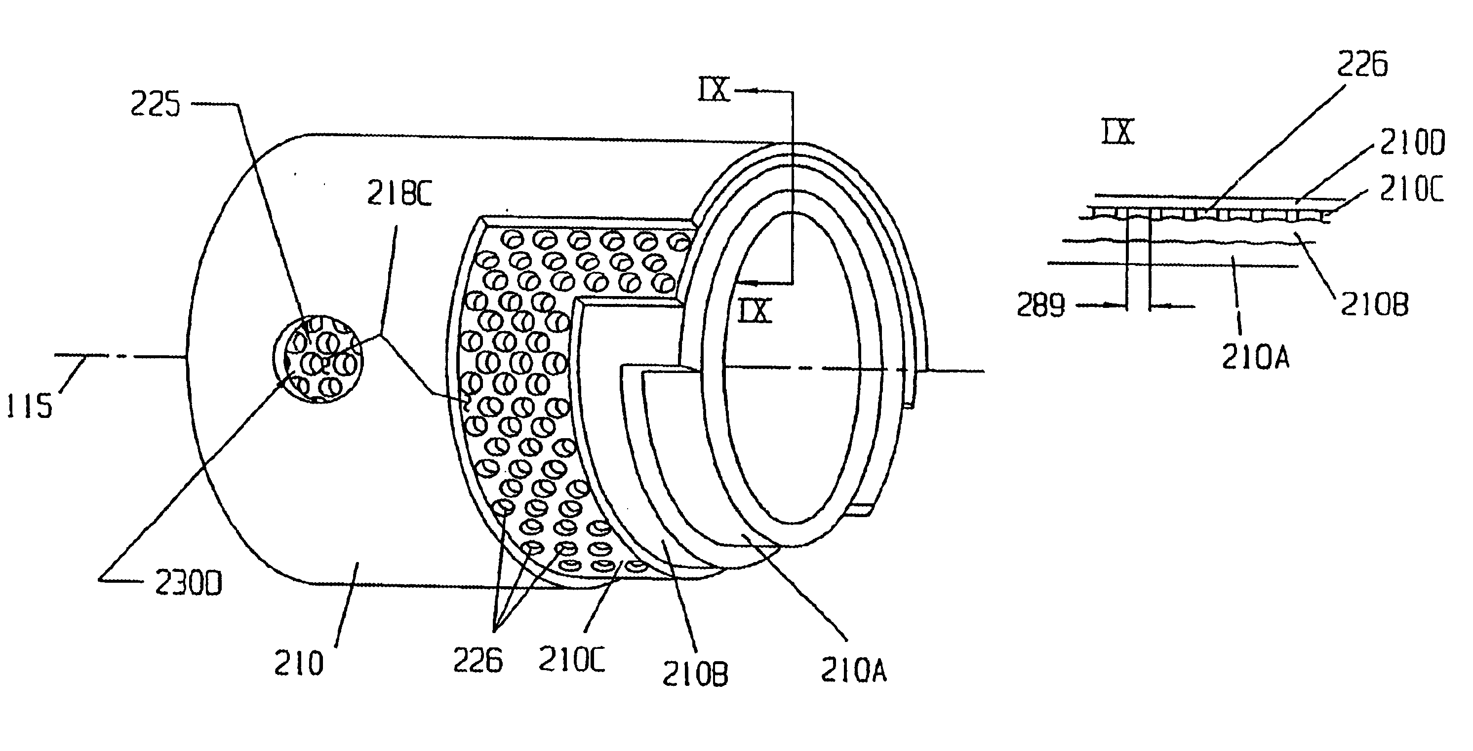
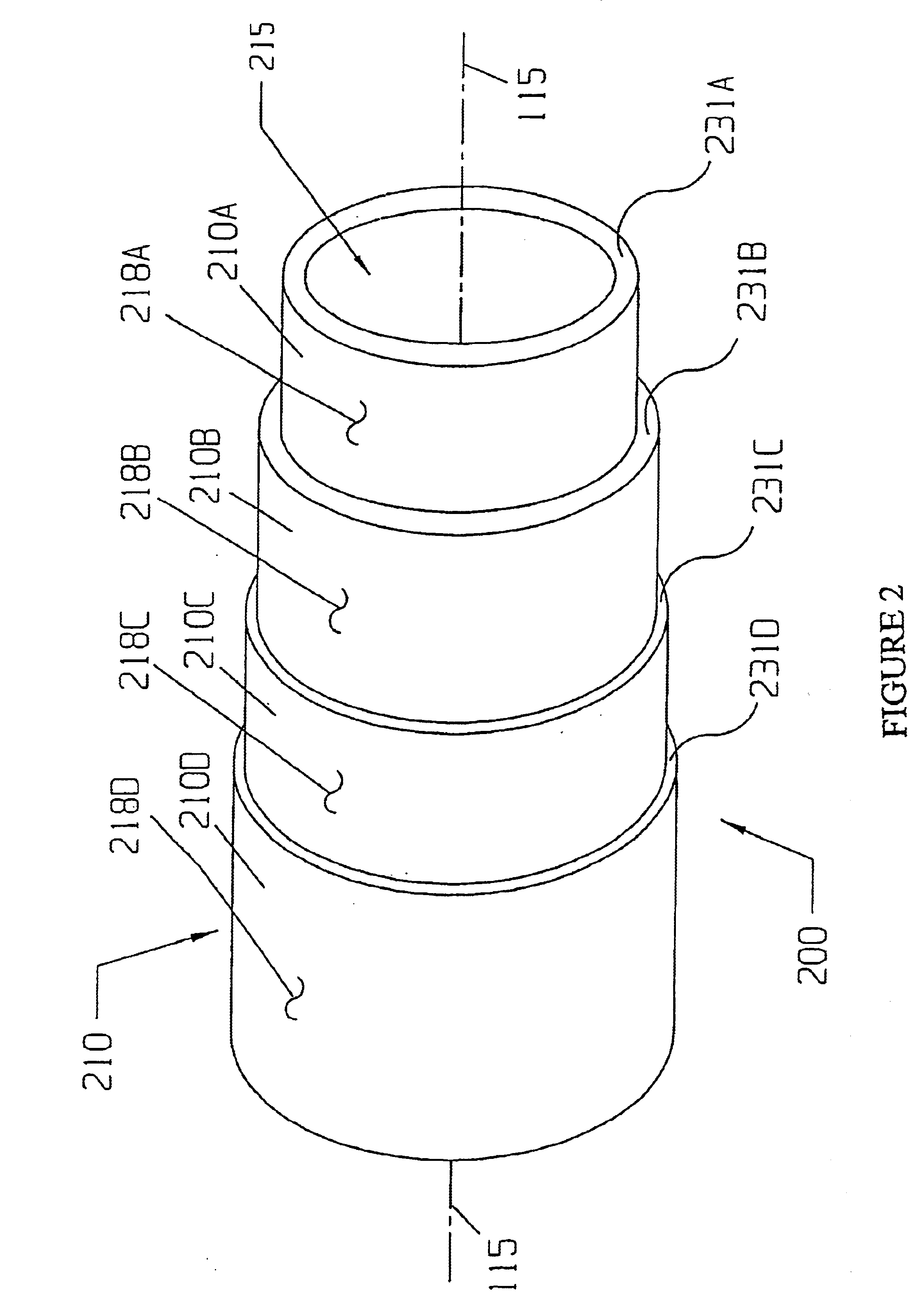
The invention disclosed herein incorporates novel engineering criteria into the design and fabrication of well perforating guns. This criterion addresses multiple requirements. First, the gun material's (steel or other metal) ability to withstand high shocks delivered over very short periods of time (“impact strength”) created by the simultaneous detonation of multiple explosive charges (“explosive energy pulse” or “pulse”) is more important than the material's ultimate strength. This impact strength is measurable and is normally associated with steels with 200low carbon content and / or higher levels of other alloying elements such as chromium and nickel. Second the shock of the explosion transfers its energy immediately to the outside surface of the tubing. Any imperfections, including scallops, will act as stress risers and can initiate cracking and failure.

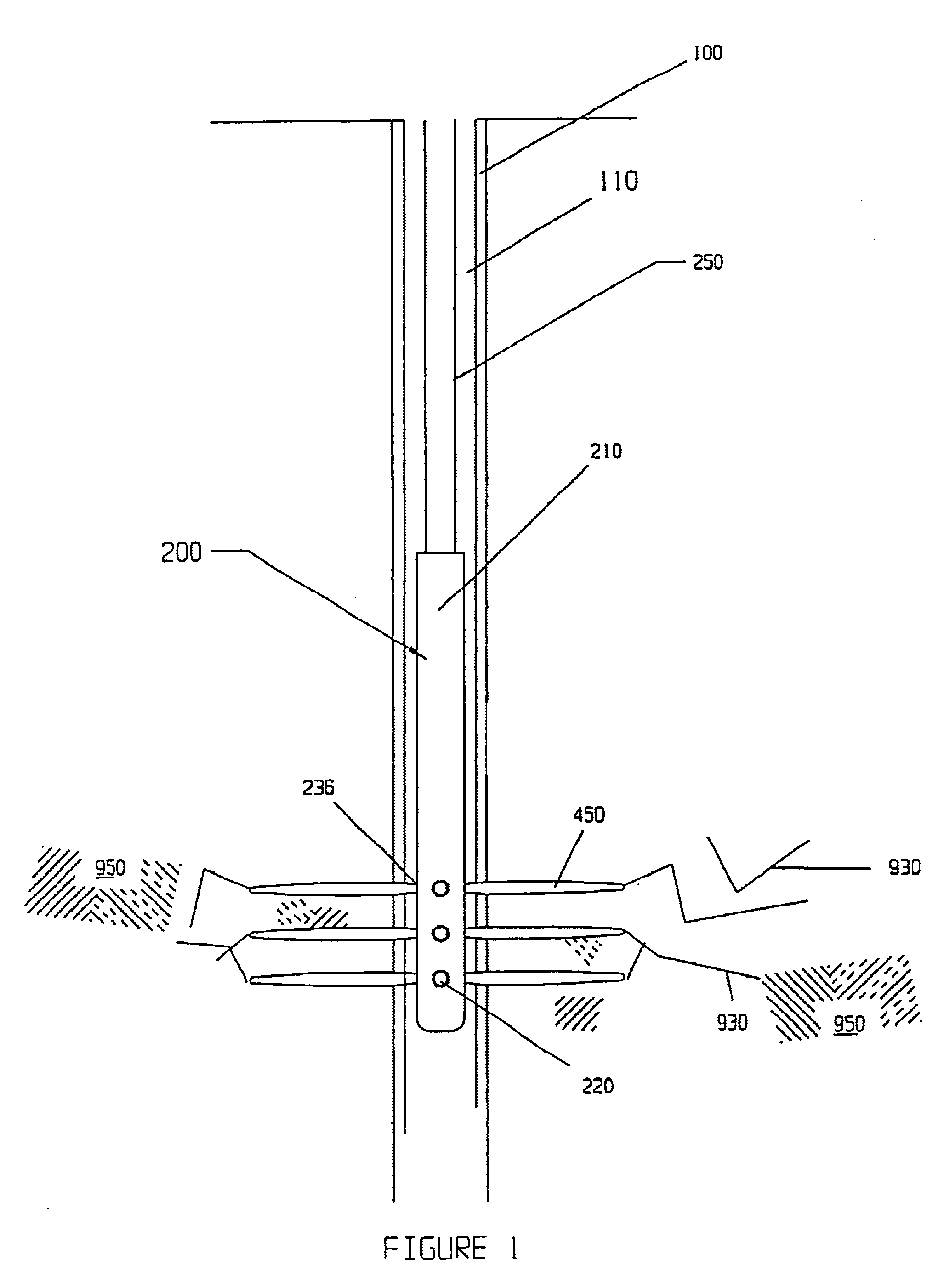
FIG. 1 illustrates the basic casing perforation operation in which the tool and fabrication method disclosed in this specifica...


PUM

PropertyMeasurementUnit
lengthaaaaaaaaaa
lengthaaaaaaaaaa
outer diameteraaaaaaaaaa

Abstract

The invention relates to a method to make a perforating gun for use in oil and natural gas wells comprising the steps of: obtaining a length of a first tube; cutting scallop holes into the first tube forming an outer layer; placing the outer layer in a holder; cutting a second tube to the approximate length of the outer layer; pulling the second tube into the outer layer forming a laminate structure having a first and second end; repeating the process for a desired number of layers in the laminate structure; machining internal structures into the laminate structure; inserting the loading tube into the laminate structure; and forming thread protectors in the first end and the second end of the laminate structure.

Description

BACKGROUNDTypically, the major component of the gun string is the “gun carrier” tube component (herein after called “gun”) that houses multiple shaped explosive charges contained in lightweight precut “loading tubes” within the gun. The loading tubes provide axial circumferential orientation of the charges within the gun (and hence within the well bore). The tubes allow the service company to preload charges in the correct geometric configuration, connect the detonation primer cord to the charges, and assemble other necessary hardware. The assembly is then inserted into the gun as shown in FIG. 2. Once the assembly is complete, other sealing connection parts are attached to the gun and the completed gun string is lowered into the well bore by the conveying method chosen.The gun is lowered to the correct down-hole position within the production zone, and the chares are ignited producing an explosive high-energy jet of very short duration. This explosive jet perforates the gun and wel...

Claims


Application Information

Patent Timeline
Patent Type & Authority Patents(United States)
IPC IPC(8): E21B43/117E21B43/11E21B43/119F42B1/00F42B1/02F42B12/76F42B12/00
CPCE21B43/117E21B43/119F42B12/76F42B1/02Y10T29/49879
Inventor KASH, EDWARD CANNOY
Owner KASH EDWARD CANNOY
Why Eureka
Try Eureka