System for drilling oil and gas wells using a concentric drill string to deliver a dual density mud

a drilling string and concentric technology, applied in the direction of drilling/well accessories, sealing/packing, survey, etc., can solve the problems of obstructing the wellbore, slipping and settle of cuttings and debris particles, and slow annular velocity for return, so as to reduce/increase the density of mud

Inactive Publication Date: 2006-08-22
DUAL GRADIENT SYST
View PDF21 Cites 64 Cited by
  • Summary
  • Abstract
  • Description
  • Claims
  • Application Information

AI Technical Summary

Benefits of technology

[0038]It is also an object and feature of the subject invention to provide a system of decreasing / increasing the density of mud in a concentric riser system with subsea or surface BOP's.
[0041]It is yet a further object and feature of the present invention to increase the return mud annular velocity by providing an oversized drill pipe having an outer diameter ranging between 6¾″, to 9⅞″.

Problems solved by technology

Typically, this is problematic where the hole diameter is large—such as the surface casing hole.
This results in a slower annular velocity for return mud flowing through these zones.
This is referred to as “critical velocity.” If the annular velocity of the return mud falls below the critical rate, then there will be a risk that the cuttings and debris particles will slip and settle thus forming bridges that may obstruct the wellbore.
Furthermore, the annular velocity of the return mud must be maintained at a laminar level to avoid turbulent flow which could be damaging to the formation itself, and also increase the equivalent circulating density unnecessarily.
This is further complicated when drilling in deep water or ultra deep water because of the pressure on the sea floor by the water above it.
When the mud density is insufficient, the gases or fluids in the borehole can cause the mud to decrease in density and become so light that a kick occurs.
Kicks are a threat to drilling operations and a significant risk to both drilling personnel and the environment.
However, the primary method for minimizing the risk of a blowout condition is the proper balancing of the drilling mud density to maintain the well in an overbalanced condition at all times. While BOP's can contain a kick and prevent a blowout from occurring thereby minimizing the damage to personnel and the environment, the well is usually lost once a kick occurs, even if contained.
However, during overbalanced drilling, the drilling mud may penetrate the formation from the wellbore.
Moreover, too much overbalanced drilling slows down the drilling process.
Alternatively, in some cases, underbalanced drilling has been attempted in order to increase the drilling rate and to reduce drilling mud penetration into the formation.
Accordingly, during underbalanced drilling, the fluids within the pore spaces of the reservoir formation actually flow into the wellbore.
Furthermore, deep water and ultra deep water drilling has its own set of problems coupled with the need to provide a high density drilling mud in a wellbore that starts several thousand feet below sea level.
This system is expensive to install, as it requires separate lines, expensive to maintain, and very expensive to run.
While it has been proven desirable to control drilling mud density and flow in a wellbore, during the drilling of oil and gas wells there are no prior art systems that effectively accomplish this objective.

Method used


Image

  • System for drilling oil and gas wells using a concentric drill string to deliver a dual density mud
  • System for drilling oil and gas wells using a concentric drill string to deliver a dual density mud
  • System for drilling oil and gas wells using a concentric drill string to deliver a dual density mud

Examples


Embodiment Construction

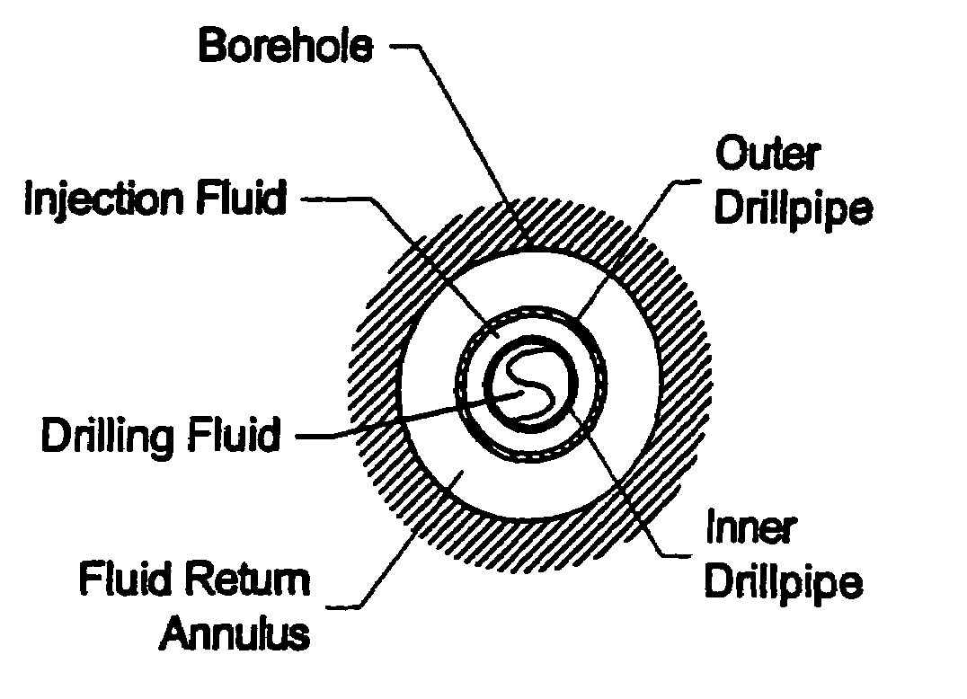
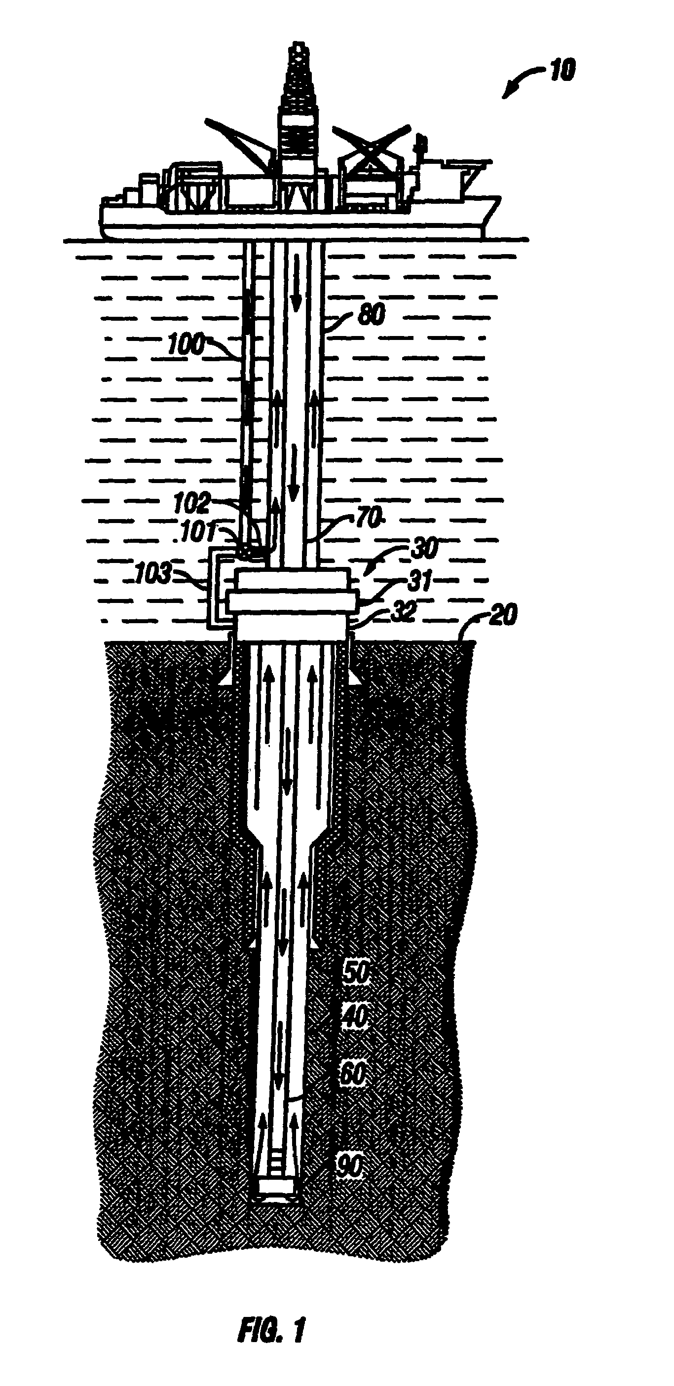
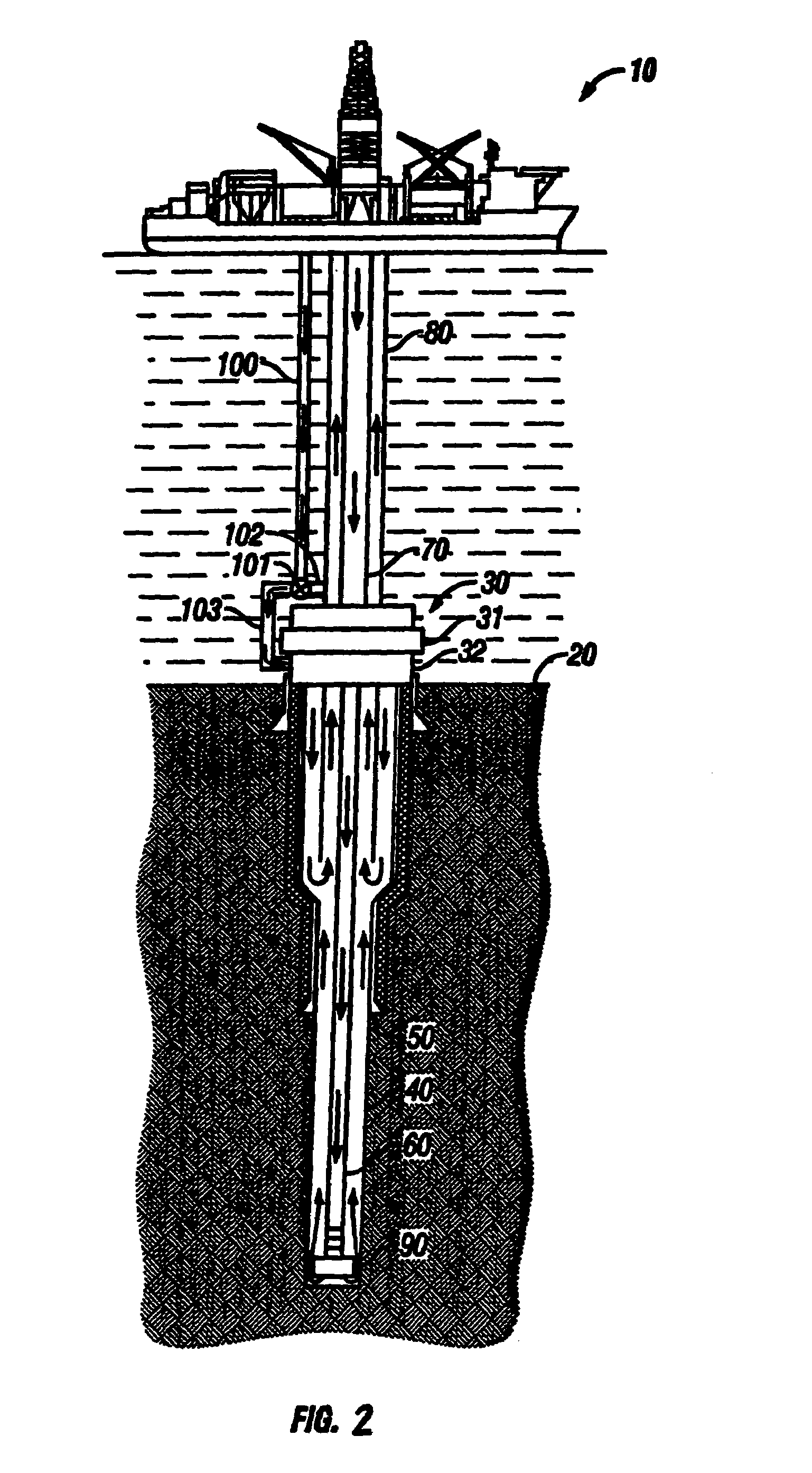
[0063]With respect to FIGS. 1–2, a mud recirculation system for use in deepwater (i.e., beyond the continental shelf) offshore drilling operations to pump drilling mud: (1) downward through a drill string to operate a drill bit thereby producing drill cuttings, (2) outward into the annular space between the drill string and the formation of the wellbore where the mud mixes with the cuttings, and (3) upward from the wellbore to the surface via a riser in accordance with the present invention is shown. A drilling unit 10 is provided from which drilling operations are performed. The drilling unit 10 may be an anchored floating platform or a drill ship or a semi-submersible drilling unit. A series of concentric strings runs from the drilling unit 10 to the sea floor or seabed 20 and into a stack 30. The stack 30 is positioned above a wellbore 40 and includes a series of control components, generally including one or more blowout preventers or BOP's 31. The concentric strings include cas...


PUM


Abstract

A system for controlling drilling mud density at a location either at the seabed (or just above the seabed) or alternatively below the seabed of wells in offshore and land-based drilling applications is disclosed. The present invention combines a base fluid of lesser / greater density than the drilling fluid required at the drill bit to drill the well to produce a combination return mud in the riser. By combining the appropriate quantities of drilling mud with a light fluid, a riser mud density at or near the density of seawater may be achieved to facilitate transporting the return mud to the surface. Alternatively, by injecting the appropriate quantities of heavy fluid into a light return mud, the column of return mud may be sufficiently weighted to protect the wellhead. At the surface, the combination return mud is passed through a treatment system to cleanse the mud of drill cuttings and to separate the drilling fluid from the base fluid. The present invention further includes a control unit for manipulating drilling fluid systems and displaying drilling and drilling fluid data.

Description

CROSS-REFERENCE TO RELATED APPLICATIONS[0001]The present application is a continuation of U.S. patent application Ser. No. 10 / 622,025 filed on Jul. 17, 2003, which is a continuation-in-part of U.S. patent application Ser. No. 10 / 390,528 filed on Mar. 17, 2003, now U.S. Pat. No. 6,926,101 which is a continuation-in-part of U.S. patent application Ser. No. 10 / 289,505 filed on Nov. 6, 2002, now U.S. Pat. No. 6,843,331 which is a continuation-in-part of U.S. patent application Ser. No. 09 / 784,367, filed on Feb. 15, 2001, now U.S. Pat. No. 6,536,540.BACKGROUND OF THE INVENTION[0002]1. Field of the Invention[0003]The subject invention is generally related to systems for delivering drilling fluid (or “drilling mud”) for oil and gas drilling applications. More particularly, the present invention is directed to a system for controlling the density and flow of drilling mud in offshore (deep and shallow water) and land-based oil and gas drilling applications.[0004]2. Description of the Prior A...

Claims


Application Information

Patent Timeline
Patent Type & Authority Patents(United States)
IPC IPC(8): E21B29/12E21B7/12E21B7/128E21B21/00E21B21/06E21B21/08E21B21/10E21B33/035E21B33/076E21B33/08
CPCE21B21/001E21B21/063E21B21/08E21B33/0355E21B33/076E21B33/085E21B21/10E21B2021/006E21B21/085E21B21/082
Inventor DEBOER, LUC
Owner DUAL GRADIENT SYST
Why Eureka
Try Eureka