Log bander apparatus and method

a bander and banding technology, applied in the field of log bander apparatus and method, can solve the problems of difficult manufacturing and repair, complex handling, manipulating, and packaging products, and achieve the effect of easy separation

Inactive Publication Date: 2005-03-15
C G BRETTING MFG
View PDF72 Cites 10 Cited by
  • Summary
  • Abstract
  • Description
  • Claims
  • Application Information

AI Technical Summary

Benefits of technology

Any number of turret clamps can be employed in the present invention. In some embodiments, multiple turret clamps are employed for significantly increasing the output of packaged logs from the apparatus. Also, some embodiments have extendible and retractable turret clamps for improved turret clamp positioning with respect to the various systems in the apparatus. Because the turret and turret clamps can move logs to different stations and systems in the apparatus, the various systems in the apparatus are much more accessible for assembly, maintenance, repair, and jam removal.
The sheets of wrap material can be perforated so that when a log contacts the sheet of wrap material, the sheet of wrap material can be more easily separated from the wrap material source. In other embodiments, cutting elements are located between the log conveyor first and second positions and are operable to cut the wrap material so that the sheet of wrap material can be drawn into the shuttle by the log. This motion can cause the logs to be at least partially wrapped in the sheets of wrap material.
As mentioned above, in some embodiments the logs drag sheets of wrap material away from the wrap conveyor and onto the shuttle. The shuttle can be adapted to receive the logs and the sheets of wrap material, and can be further adapted to wrap the wrap material around the logs as the logs enter the shuttle, thereby more fully enclosing the log in the wrap material. In some cases, the shuttle includes tuckers which wrap the wrap material around the log, thereby insuring that the wrap material is correctly positioned with respect to the log. More particularly, the tuckers can position the wrap material around the trailing edge of the log to ensure that the log is properly surrounded with wrap material.

Problems solved by technology

However, certain applications in which the product to be packaged is compressed prior to or during packaging can present machine design problems unique to those applications.
Also, many applications require packaging speeds demanding fast and efficient machine operation.
Packaging systems and devices capable of performing packaging operations at high speed and which handle, manipulate, and package product are typically quite complex and difficult to manufacture and repair.
In addition, those systems and devices which handle, manipulate, and package compressed product can present unique design, maintenance, and repair challenges.
Due to their complexity, conventional product packaging systems are typically very compact and crowded, and therefore do not permit easy access to different system components therein for repair and maintenance.
Such systems are also therefore difficult to clear when product jams or misfeeds occur or when system adjustments must be made.
The increased speeds at which existing product packaging systems are called to operate presents another problem.
Therefore, many conventional stacked product packaging systems simply cannot be used at the very high product speeds becoming more common in connected paper processing and handling equipment.
The size and length of some product (e.g., logs of stacked paper products, rolls of product, and the like) presents still another problem.
In applications in which the logs are particularly large, conventional packaging apparatuses have difficulty in wrapping the logs with potentially large sheets of wrapping material.
In particular, it has often been difficult to insert large pieces of wrapping material into the wrapping apparatus without wrinkling, folding or tearing the wrapping material.
Additionally, these relatively large sheets of wrapping material can make misfeeds and jamming even more likely.

Method used


Image

  • Log bander apparatus and method
  • Log bander apparatus and method
  • Log bander apparatus and method

Examples


second embodiment

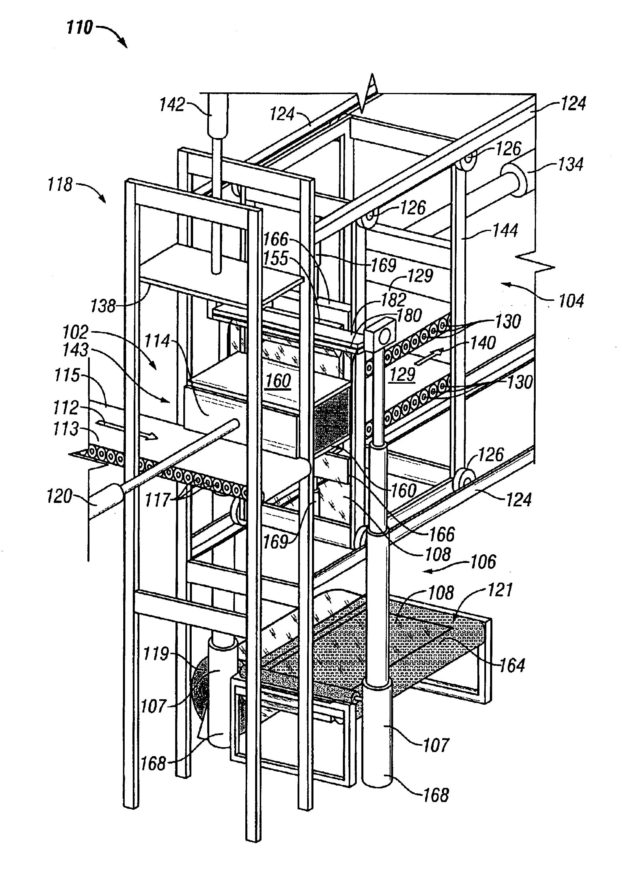
FIGS. 12-15 illustrate the present invention in which the log packaging apparatus 110 includes a compression station 102, a shuttle 104, and a wrap conveyor 106 which cooperate to wrap a log L in a sheet of wrap material 108. By way of illustration only, the following description and accompanying figures show packaging operations in which the log L is wrapped in a sleeve wrapper. In other embodiments of the present invention, the apparatus 110 can package, bind, wrap, seal, tie, and perform other packaging operations as described in greater detail above with respect to the first illustrated embodiment. Additionally, the following description describes a packaging process which utilizes a single sheet of wrapping material 108. However, other embodiments of the present invention can use more than one sheet of wrap material 108, strips of wrap material, straps of wrap material, etc. (as also described above).

The embodiment of the present invention illustrated in FIGS. 12-15 is similar ...

first embodiment

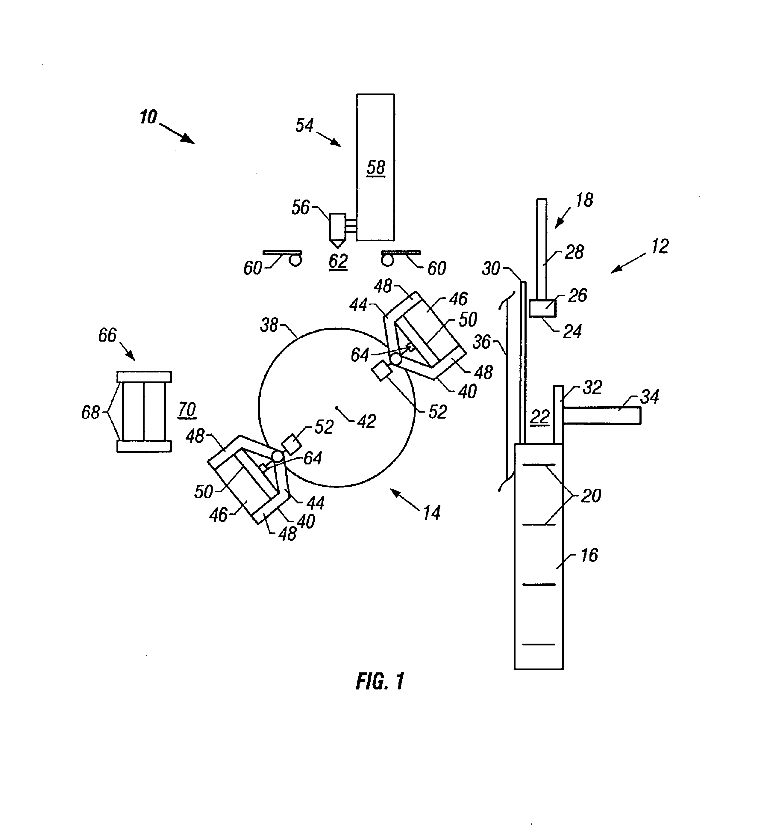
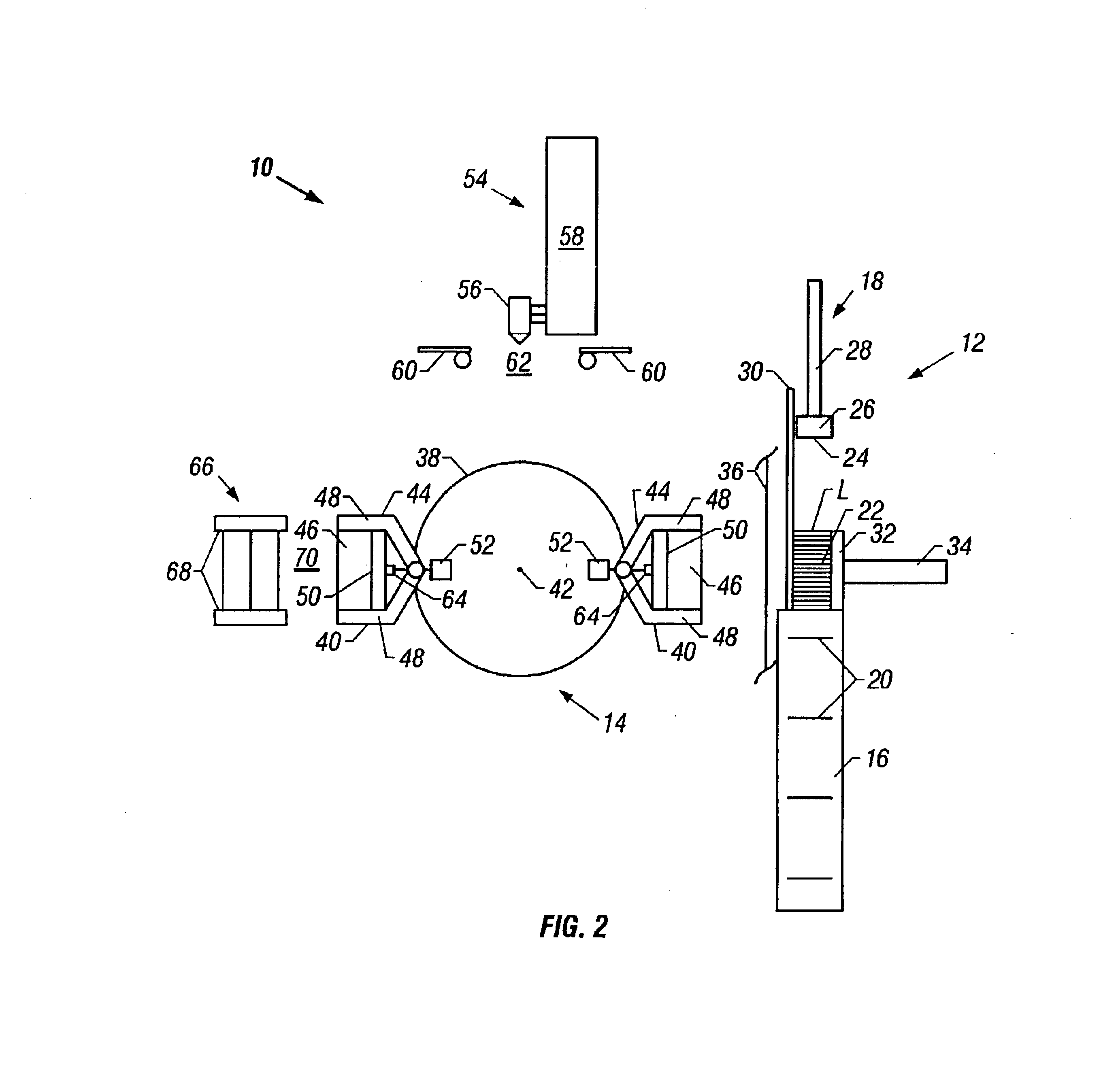
The embodiments described above and illustrated in the figures are presented by way of example only and are not intended as a limitation upon the concepts and principles of the present invention. As such, it will be appreciated by one having ordinary skill in the art that various changes in the elements and their configuration and arrangement are possible without departing from the spirit and scope of the present invention as set forth in the appended claims. For example, and noted above, the present invention can be used to package product found in forms other than stacked form, such as rolled product (e.g., toilet paper, paper towels, etc.), bundled product (e.g., banded or unbanded stacks of newspaper, folded boxes, bags, etc.), or even fiber or particulate form (e.g., food product, wood chips, etc.). The shape and design of various portions of the log packaging apparatus 10 can therefore take forms better suited for the product being packaged. For example, in the first embodimen...


PUM

PropertyMeasurementUnit
adhesiveaaaaaaaaaa
distanceaaaaaaaaaa
speedsaaaaaaaaaa

Abstract

A log packaging apparatus for packaging logs using a turret or a shuttle. The turret or shuttle can be used in conjunction with a wrap conveyor. The turret system can include a rotatable turret with at least one clamp movable into different positions in the apparatus, a log station at which logs are received, and a log ejector for ejecting logs from the log station into clamps of the turret. Logs can be ejected from the log station, through wrap material, and into the turret clamps. In other embodiments, a wrap conveyor inserts wrap material between a shuttle and a log station at which logs are received. Logs in such embodiments can pass from the log station to the shuttle through the wrap material.

Description

BACKGROUND OF THE INVENTIONNumerous systems and devices exist for packaging product in a variety of ways, including without limitation banders, wrapping machines, sleeve wrap machines, and the like. However, certain applications in which the product to be packaged is compressed prior to or during packaging can present machine design problems unique to those applications. Also, many applications require packaging speeds demanding fast and efficient machine operation. Packaging systems and devices capable of performing packaging operations at high speed and which handle, manipulate, and package product are typically quite complex and difficult to manufacture and repair. In addition, those systems and devices which handle, manipulate, and package compressed product can present unique design, maintenance, and repair challenges.Due to their complexity, conventional product packaging systems are typically very compact and crowded, and therefore do not permit easy access to different syste...

Claims


Application Information

Patent Timeline
Patent Type & Authority Patents(United States)
IPC IPC(8): B65B63/00B65B63/02B65B11/10B65B11/40B65B13/20B65B25/14B65B51/02
CPCB65B11/10B65B11/40B65B63/02B65B25/145B65B51/023B65B25/14
Inventor DAOUST, JAMES M.YACHINICH, JOSEPH A.COUTURIER, DENNIS P.
Owner C G BRETTING MFG
Why Eureka
Try Eureka