Front body structure for vehicle

a front body and vehicle technology, applied in the direction of roofs, vehicular safety arrangments, transportation and packaging, etc., can solve the problems of the front wheel not being able to rotate and the front wheel being unable to rota

Inactive Publication Date: 2005-03-15
NISSAN MOTOR CO LTD
View PDF16 Cites 80 Cited by
  • Summary
  • Abstract
  • Description
  • Claims
  • Application Information

AI Technical Summary

Benefits of technology

Under the above circumstance, it is an object of the present invention to provide a front body structure which is capable of avoiding a concentration of a collision load, which has been exerted to a front wheel (or front wheels) by the vehicle front collision, on the front end of the side sill.

Problems solved by technology

In the above-mentioned front body structure, however, there is a tendency that when the vehicle has a front collision, at least one front wheel interferes with only the front end of the side sill directly, so that a collision load is concentrated on the side sill excessively, causing its great deformation.
Additionally, when the front wheel is steered inwardly in the vehicle's width direction since the vehicle has a collision from oblique forward, a problem arises in that the front wheel cannot always interfere with any vehicle-body structural member disposed inside the front wheel, for example, a side member.

Method used


Image

  • Front body structure for vehicle
  • Front body structure for vehicle
  • Front body structure for vehicle

Examples


first embodiment

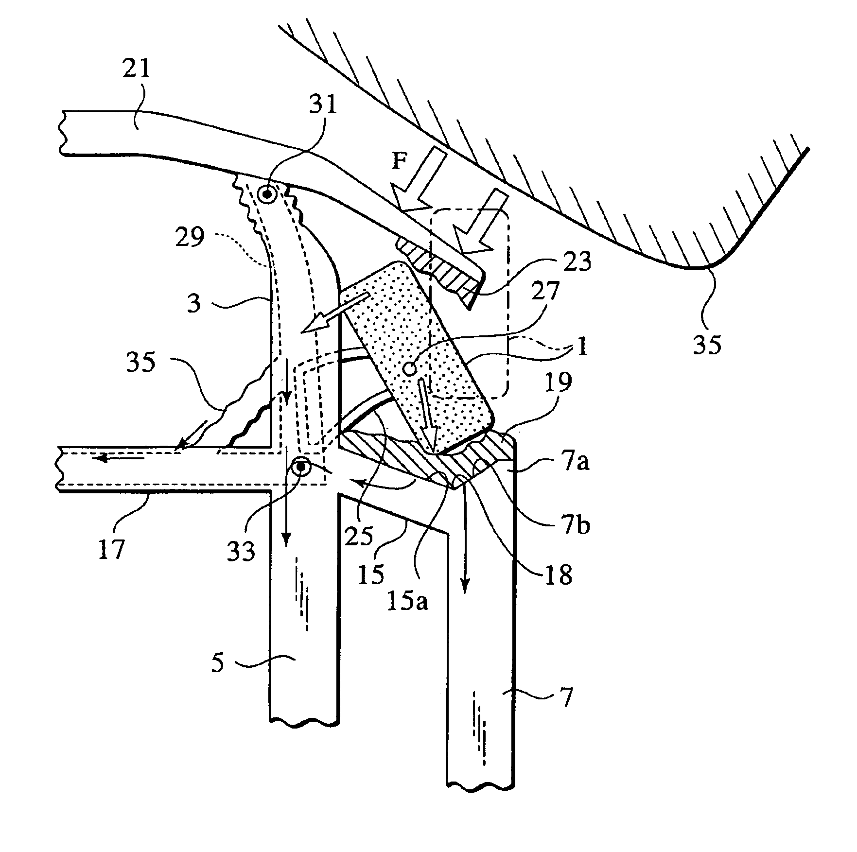
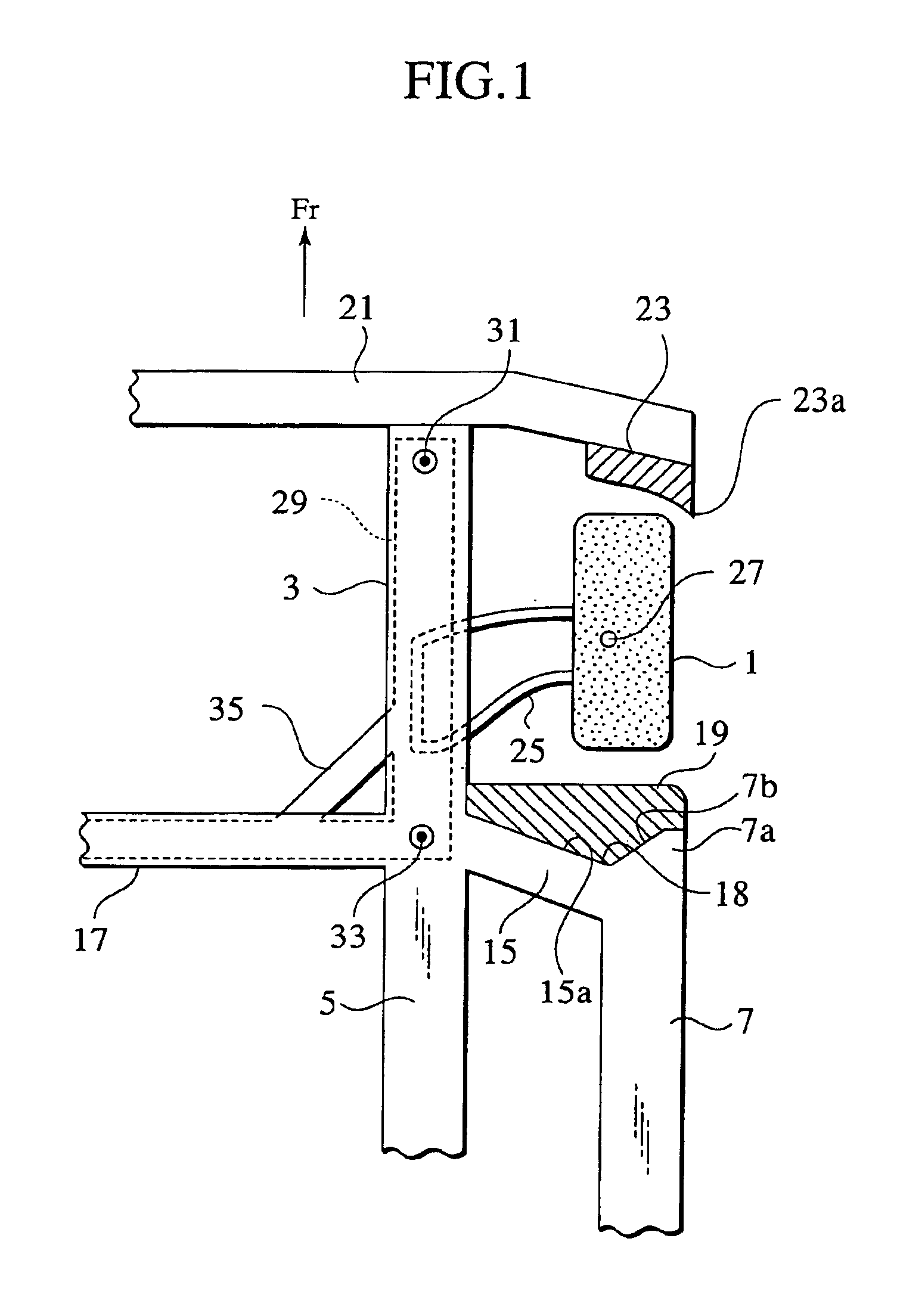
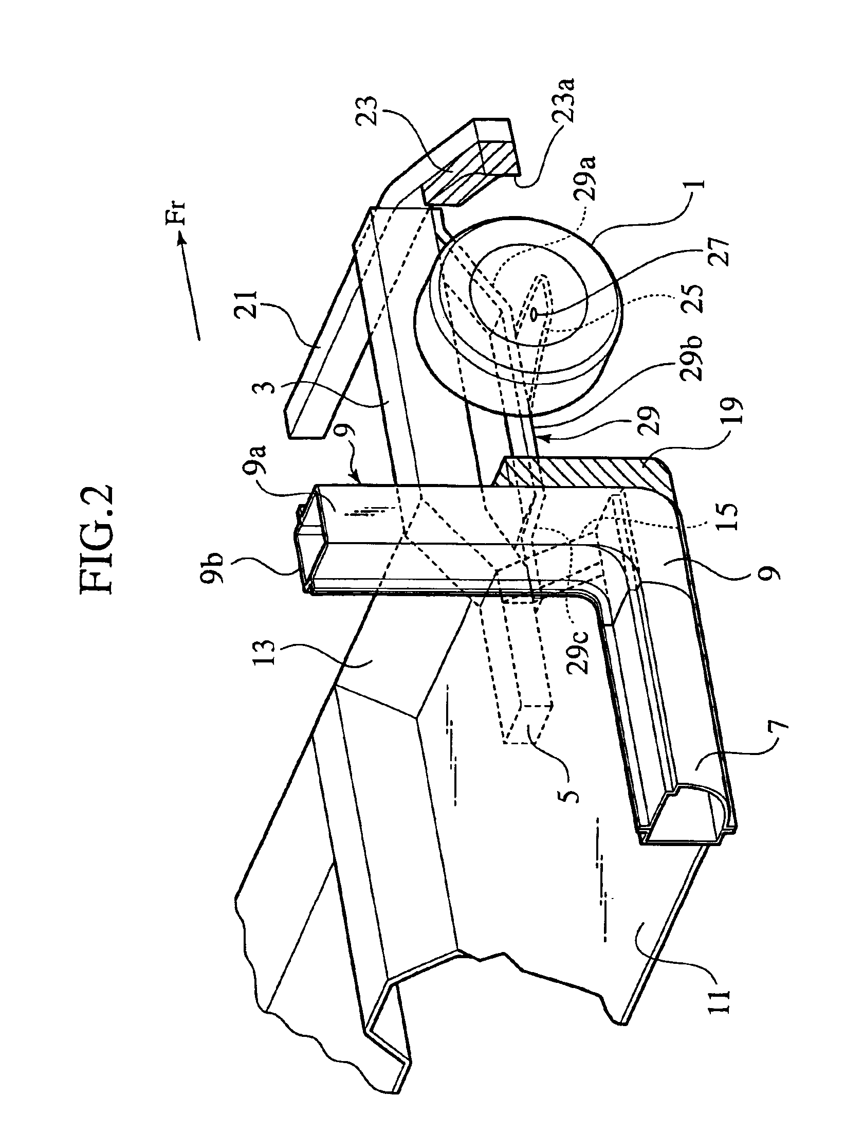
In the figures, FIG. 1 is a plan view of a front structure of a vehicle body in accordance with the invention. FIG. 2 is a perspective view of FIG. 1, while FIG. 3 is a perspective view of an automobile equipped with the front structure of FIG. 1. In common with FIGS. 1 and 2, a direction shown with an arrow Fr designates a front side of the vehicle body. Note, FIGS. 1 and 2 only show the front structure on the right side of the vehicle body; nevertheless the front structure on the left side of the vehicle body is identical to the same on the right side of the vehicle body because of its symmetrical arrangement. Therefore, the following descriptions will be represented by an example of the front structure on the right side of the vehicle body.

Inside a front wheel 1 in the vehicle width direction, there is a front side member 3 (as the vehicle-body structural member) extending in the fore-and-aft direction of the vehicle body. The front side member 3 has its rear end joined to an ext...

second embodiment

FIGS. 10A and 10B illustrate the present invention. According to this embodiment, there is provided, at a position of the section X—X of the front pillar 9 of FIG. 6, a plate member 41 (as external reinforcing member) between a “front pillar” lower-and-outer member 9a and the rear energy absorbing member 19. In the figures, reference numeral 9b denotes a “front pillar” lower-and-inner member.

Corresponding to the front pillar 9, the rear energy absorbing member 19 is shaped so as to have a notch face 19a allowing a triangular space 43 to be defined between the member 19 and the “front pillar” lower-and-outer member 9a. The above plate member 41 is arranged so as to cover the notch face 19a. The plate member 41 has one end welded to the “front pillar” lower-and-outer member 9a at its connection with the “front pillar” lower-and-inner member 9b and also has the other end welded to an inner face of a panel member 45.

Therefore, according to the second embodiment, even when the front coll...

fourth embodiment

FIGS. 12A and 12B show the invention. According to the embodiment, the rear energy absorbing member 19 in front of the side sill 7 is formed in such a manner that the same member's thickness in the vehicle's fore-and-aft direction gradually increases as directing from the member's upper part corresponding to the front pillar 9 to the member's lower part corresponding to the side sill 7.

As shown in FIG. 12B, at the vehicle front collision, the rear energy absorbing member 19 is apt to be deformed mainly at the member's lower part corresponding to the side sill 7. Therefore, by increasing the thickness of the member's lower part, the collision load on the front wheel 1 can be transmitted as an axial force to the side sill 7 mainly, whereby it is possible to reduce a load on the front pillar 9 and also a bending moment generating in the base of the front pillar 9.


PUM


Abstract

A front body structure is provided to restrain a collision load, which has been applied on a front wheel by a vehicle front collision, to be concentrated on a front end of a side sill excessively. In the structure, a front energy absorbing member 23 is attached to a back face of a lateral end of a bumper 21. A recess 18 is formed by a front end of the side sill 7 and a front face of an outrigger 15. A rear energy absorbing member 19 is attached into the recess 18. The outrigger 15 connects the side sill 7 with a front side member extension 5 joined to the rear end of a front side member 3. At the vehicle front collision, the front energy absorbing member 23 interferes with the right-and-front part of the front wheel 1 to allow the left-and-front part of the front wheel 1 to interfere with the side face of the front side member 3 and also allow the rear part of the wheel 1 to interfere with the rear energy absorbing member 19.

Description

TECHNICAL FIELDThe present invention relates to a front body structure for vehicle.BACKGROUND ARTJapanese Patent Publication (kokai) No. 11-342869 discloses a front body structure for vehicle. This front body structure includes a pair of side sills arranged on both sides of a lower part of a vehicle body to extend in the vehicle's fore-and-aft direction. Further, a front pillar is arranged to stand on a front end of each side sill. The front body structure is adapted so as to disperse a collision load, which has been transmitted through the front wheel at the vehicle front collision, by the side sill itself.In the above-mentioned front body structure, however, there is a tendency that when the vehicle has a front collision, at least one front wheel interferes with only the front end of the side sill directly, so that a collision load is concentrated on the side sill excessively, causing its great deformation. Additionally, when the front wheel is steered inwardly in the vehicle's wi...

Claims


Application Information

Patent Timeline
Patent Type & Authority Patents(United States)
IPC IPC(8): B62D21/15B62D21/02B62D21/04B60R19/00B62D25/20B62D25/04
CPCB60R19/00B62D21/04B62D21/155B62D21/152B62D21/15B60R2019/007
Inventor MIYASAKA, HIROYUKI
Owner NISSAN MOTOR CO LTD
Why Eureka
Try Eureka