Vehicle front body structure

a front body and vehicle technology, applied in the direction of bumpers, roofs, vehicular safety arrangments, etc., can solve the problems of high repair costs, and achieve the effect of ensuring the strength and rigidity of the cross member and high repair costs

Active Publication Date: 2005-03-15
NISSAN MOTOR CO LTD
View PDF5 Cites 14 Cited by
  • Summary
  • Abstract
  • Description
  • Claims
  • Application Information

AI Technical Summary

Benefits of technology

With the above-mentioned vehicle front body structure in which the cross member is connected to the bumper reinforcing member to ensure the strength and rigidity of the cross member, when the bumper reinforcing member is deformed due to an impact load from the front of the vehicle body, the cross member is also deformed, thus causing high repair costs.
The present invention was made in the light of this problem. An object of the present invention is to provide a vehicle front body structure which suppresses deformation of a cross member due to a load from the front of a vehicle body.

Problems solved by technology

With the above-mentioned vehicle front body structure in which the cross member is connected to the bumper reinforcing member to ensure the strength and rigidity of the cross member, when the bumper reinforcing member is deformed due to an impact load from the front of the vehicle body, the cross member is also deformed, thus causing high repair costs.

Method used


Image

  • Vehicle front body structure
  • Vehicle front body structure
  • Vehicle front body structure

Examples


first modification

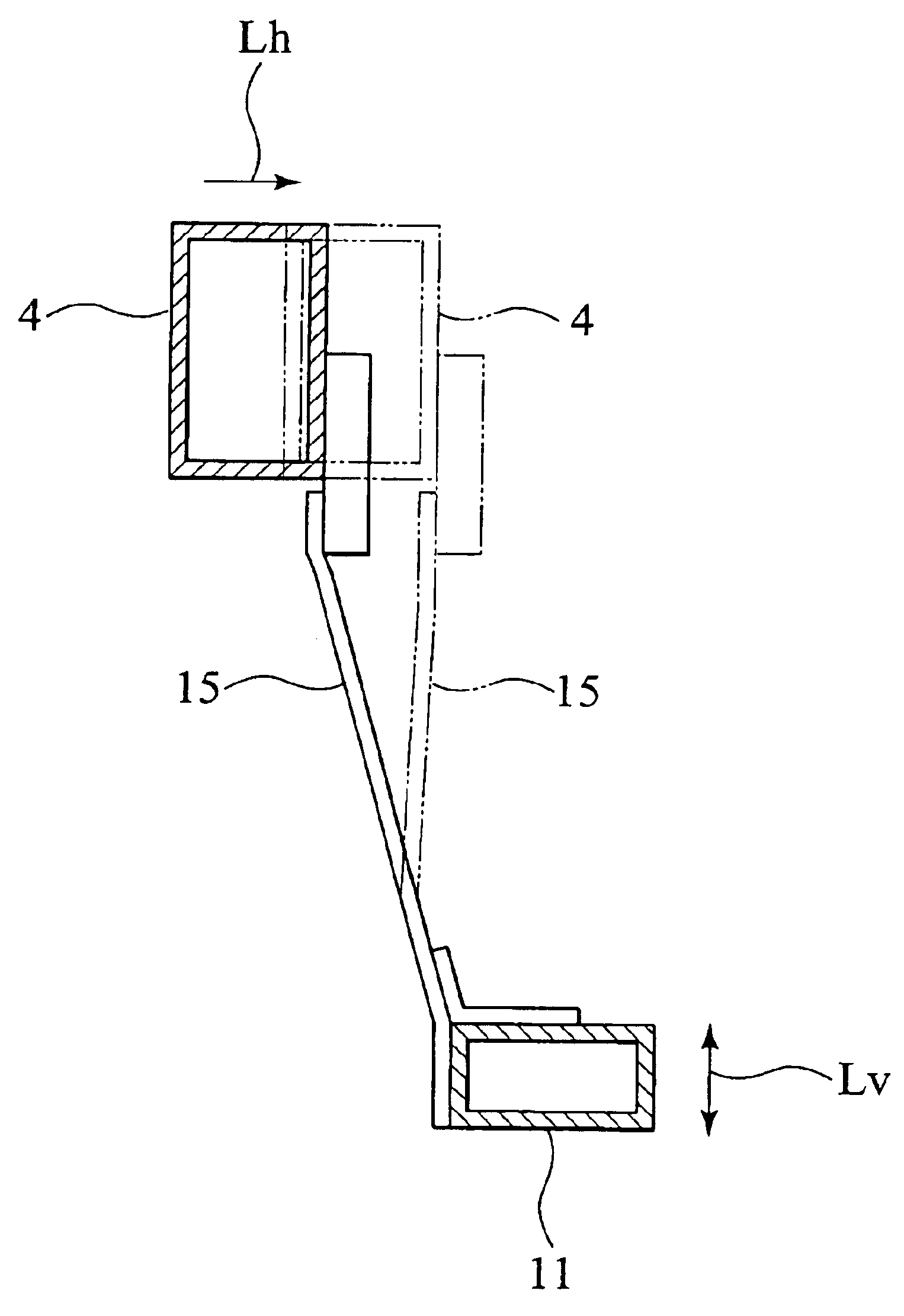
FIG. 4 shows a first modification of this embodiment, in which the connecting member 15 is formed in a substantially flat-plate shape with its width substantially in the vehicle transverse direction 5. This connection member 15 is directly connected to the rear side wall of the bumper reinforcing member 4 and a front face of the cross member 11 by spot welding or the like at welding points 41 of both end portions thereof. In this construction, the connection strength between the bumper reinforcing member 4 and the cross member 11 through the connecting member 15 can be increased in the vertical direction 12 and reduced in the vehicle longitudinal direction 1. For example, the connection strength at the connection point of the connecting member 15 and the bumper reinforcing member 4, or the strength of the connecting member 15 itself, against a load applied to the bumper reinforcing member 4 in the vehicle longitudinal direction 1, can be reduced, while rigidity of integrated members...

second modification

FIG. 5 shows a second modification of this embodiment, in which the connecting member 15 in a flat-plate shape having its width substantially in the vehicle transverse direction 5, is formed to have thereon a rib 42 extending between the top and bottom connection points of the connecting member 15 to the vicinities of the connection points thereof. With the changed cross-section of the connecting member 15 by provision of this rib 42, a load that is present in the connecting member 15 when a load is applied to the bumper reinforcing member 4 in the vehicle longitudinal direction 1, concentrates at each of the top and bottom connection points thereof. The connection strength at the connection points of the connecting member 15 in the vehicle longitudinal direction 1 is thus surely reduced. In this construction, the connection strength between the bumper reinforcing member 4 and the cross member 11 through the connecting member 15 can be increased in the vertical direction 12 and redu...


PUM


Abstract

A vehicle front body structure which includes: a pair of side members extending in a vehicle longitudinal direction; a bumper reinforcing member connected to front ends of the side members; a cross member connected to bottoms of the side members in the vicinities of the front ends thereof; and a connecting member connected to the bumper reinforcing member and the cross member. Connection strength between the connecting member and the bumper reinforcing member in the vehicle longitudinal direction is lower than a flexural strength of the cross member in the vehicle longitudinal direction.

Description

BACKGROUND OF THE INVENTION1. Field of the InventionThe present invention relates to a vehicle front body structure.2. Description of Related ArtJapanese Patent Application Laid-Open NO. 2000-177634 discloses a vehicle front body structure, in which a bumper reinforcing member connecting front ends of side members and a cross member provided below the bumper reinforcing member are connected to each other.SUMMARY OF THE INVENTIONWith the above-mentioned vehicle front body structure in which the cross member is connected to the bumper reinforcing member to ensure the strength and rigidity of the cross member, when the bumper reinforcing member is deformed due to an impact load from the front of the vehicle body, the cross member is also deformed, thus causing high repair costs.The present invention was made in the light of this problem. An object of the present invention is to provide a vehicle front body structure which suppresses deformation of a cross member due to a load from the ...

Claims


Application Information

Patent Timeline
Patent Type & Authority Patents(United States)
IPC IPC(8): B62D25/08B62D21/15
CPCB62D25/084B62D21/152
Inventor SAITOU, TSUTOMU
Owner NISSAN MOTOR CO LTD
Why Eureka
Try Eureka