Illumination apparatus and a liquid crystal projector using the illumination apparatus

a technology of illumination apparatus and liquid crystal projector, which is applied in the direction of lighting and heating apparatus, picture reproducers using projection devices, instruments, etc., can solve the problem of extremely low parallelity of luminous flux obtained via spherical reflection mirror, and achieve the effect of improving the usability of luminous flux and reducing the size of output ligh

Inactive Publication Date: 2005-03-15
RICOH KK
View PDF8 Cites 35 Cited by
  • Summary
  • Abstract
  • Description
  • Claims
  • Application Information

AI Technical Summary

Benefits of technology

Accordingly, it is a general object of the present invention to provide an illumination apparatus reducing the size of an output light utilizing optical system such as an integrator optical system and improving the usability of luminous flux originating from a light source, and a liquid crystal projector using such an illumination apparatus.
Accordingly, since the liquid crystal panel can be illuminated by luminous flux with high usability of light on the whole using the illumination apparatus described above to project the image to the screen by the projection lens system having a relatively small aperture, the whole liquid crystal projector can be made compact.

Problems solved by technology

In other word, since the arc image is present at a position away from the focal point of the reflector, it is disadvantageous that parallelism of luminous flux from the reflector 211 obtained via the spherical reflection mirror is extremely lowered as compared to light directly coming from the arc.

Method used


Image

  • Illumination apparatus and a liquid crystal projector using the illumination apparatus
  • Illumination apparatus and a liquid crystal projector using the illumination apparatus
  • Illumination apparatus and a liquid crystal projector using the illumination apparatus

Examples


first embodiment

Firstly, the present invention will be illustrated with reference to FIG. 7.

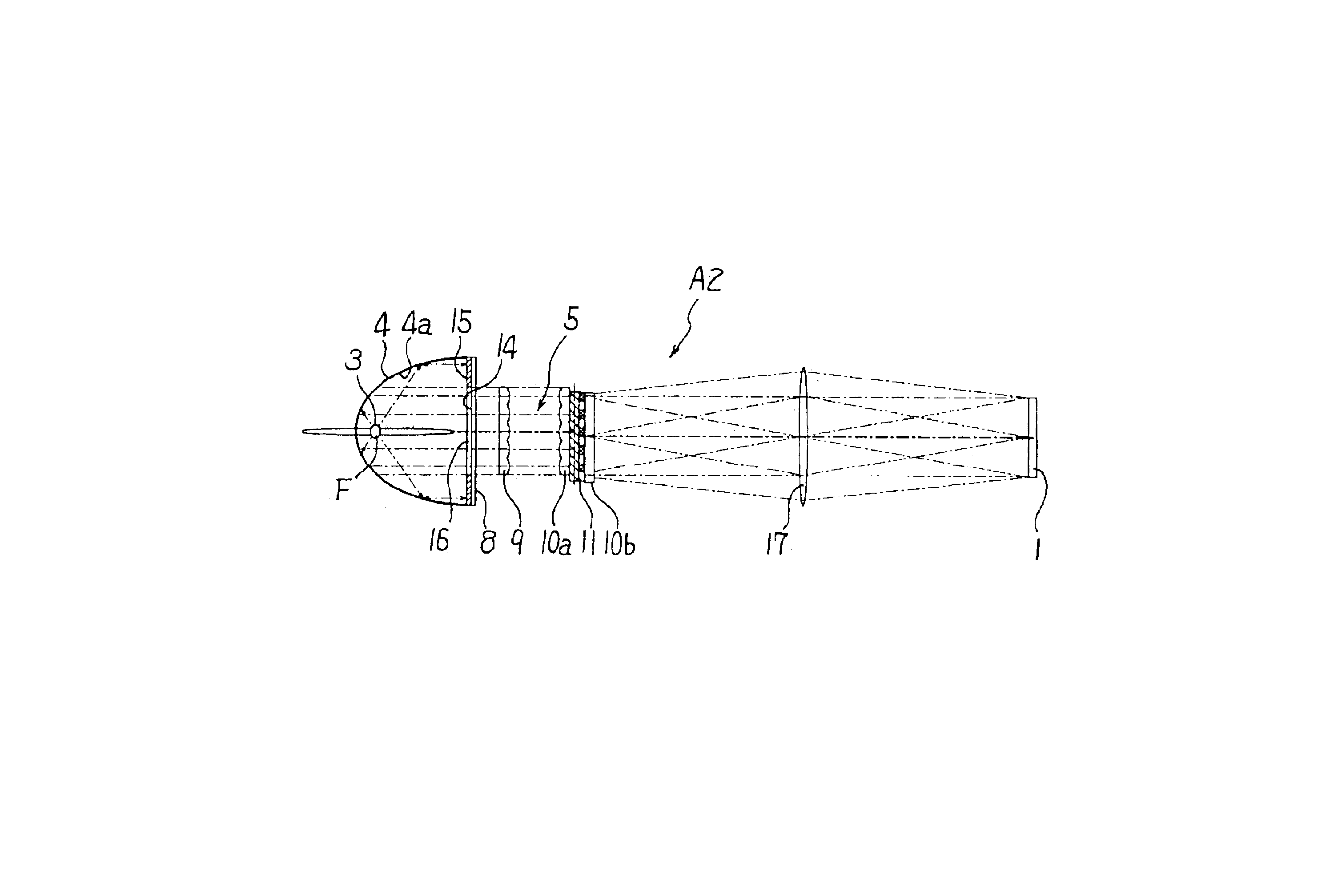
In an illumination apparatus A1 of the present embodiment, a rectangular liquid crystal panel 1 with an aspect ratio of a longitudinal side and a lateral side of 4:3 is an illuminated object and a condenser lens 2 laid on the front surface of the crystal panel transmits luminous flux with minimum diameter to a projection lens after respective liquid crystal elements receive illuminating radiation and form an image. For such liquid crystal panel 1, the illumination apparatus A1 of the present embodiment includes a light source 3 like a point source, a parabolic mirror 4 as a reflector in which the light source 3 is arranged inside, an integrator optical system 5 as an output light utilizing optical system, and a focusing lens 6.

As for the light source 3, a high-pressure mercury-vapor lamp, a metal halide lamp, and a xenon lamp, etc. have been used. The light source 3 is arranged at a focal point F of the para...

second embodiment

The second embodiment according to the present invention will be illustrated with reference to FIG. 8. The same part as the part illustrated in the first embodiment is indicated with the same numerals and the explanation about that part will be omitted. The same will be applied for each of the following embodiments.

Although the plane mirror 12 is directly formed as one unit on the inner surface of the front glass 8 in the first embodiment, the plane mirror 15 as a front mirror that is a member different from the front glass 8 is provided on the inner surface or the outer surface of the front glass 8, perpendicularly to the light axis of the collimated light for the illumination apparatus A1 in the present embodiment. The plane mirror 15 is, for example, a high-purity aluminum plate whose surface at light source side is mirror-finished. Also, a window 16 of which the shape is substantially the same as the shape of the first fly-eye lens-array 9 is formed as an aperture in the center ...

third embodiment

The third embodiment according to the present invention will be illustrated with reference to FIG. 9 and FIG. 10. In the present embodiment, only the configuration near the parabolic mirror 4 is shown. In the present embodiment, a plane mirror 15 that is a member different from the front glass 8 is arranged between the front glass 8 and the light source 3. That is, the plane mirror 15 is separated from the front glass 8 and arranged at the light-source 3 side of the front mirror 8. The size and shape of the window 16 are the same as the size and shape of the window shown in FIG. 8.

In such configuration, although luminous flux emitted from the light source 3 is substantially collimated by the parabolic mirror 4, luminous flux with divergence angles of 5° through 10° are generally included. Herein, according to the configuration like the present embodiment, before the divergence of light emitted from the light source 3 is increased, the light is reflected from the plane mirror 15 to h...


PUM


Abstract

An illumination apparatus includes a reflector including a parabolic or ellipsoidal mirror, a light source arranged near a (first) focal point of the reflector, and a front mirror having a transparent window and a mirror surface symmetrical about the light axis. Luminous flux emitted from the light source is reflected from the reflector. In the case of the parabolic mirror, the front mirror has the same size as an entrance of an output light utilizing optical system, and the luminous flux exits toward the optical system as collimated light. In the case of the ellipsoidal mirror, the front mirror is arranged between two focal points of the ellipsoidal mirror, and the luminous flux is directed toward the second focal point. However, at least one part of the luminous flux is reflected from the front mirror and returned toward the first focal point.

Description

BACKGROUND OF THE INVENTION1. Field of the InventionThe present invention relates to an illumination apparatus suitable for illuminating a rectangular object such as a liquid crystal panel, and a liquid crystal projector using such an illumination apparatus.2. Description of the Related ArtAs for an illumination optical system for uniformly illuminating a rectangular object such as a liquid crystal panel, an integrator optical system in which two fly-eye lens-arrays are combined is known from, for example, Japanese Laid-Open Patent Application No. 3-111806.The integrator optical system shown in the above patent application divides a luminous flux originating from a light source with a reflector such as a parabolic reflector, an ellipsoidal reflector and a hyperbolic reflector, by multiple rectangular focusing lenses constituting a first fly-eye lens-array to form secondary light source images. A convolution of the secondary light source images is imaged on one illuminated object thr...

Claims


Application Information

Patent Timeline
Patent Type & Authority Patents(United States)
IPC IPC(8): H04N9/31
CPCG02B27/0927H04N9/3105H04N9/315G02B19/0028H04N9/3167H04N9/3197G02B19/0047H04N9/3152
Inventor YAMAUCHI, SATOSHIFUJITA, KAZUHIROHONDA, TADASHINAGASE, OSAMU
Owner RICOH KK
Why Eureka
Try Eureka