
System for sensing the presence of a load in an oven cavity of a microwave cooking appliance

a technology for microwave cooking appliances and load sensing, which is applied in the field of microwave cooking appliances, can solve the problems of microwave energy fields damaging the interior portions of the oven cavity, damage to the internal structure of the magnetron, and food to cook unevenly, and achieves the effect of high frequency energy

Inactive Publication Date: 2005-03-15
ACP OF DELAWARE
View PDF29 Cites 59 Cited by
  • Summary
  • Abstract
  • Description
  • Claims
  • Application Information

AI Technical Summary

Benefits of technology

"The present invention is about a microwave cooking appliance with a load sensing system. The system includes a controller and a transducer that emits a high frequency energy burst into the oven cavity. The energy burst is reflected back to the transducer which then sends a signal to the controller. The controller will determine whether or not a load is present in the oven cavity based on the nature of the signal. This helps to prevent the appliance from operating if no load is detected. The load sensing system uses a piezoelectric transducer that emits an ultrasonic high frequency energy burst into the oven cavity. The reflected energy burst is converted into an electronic signal that is forwarded to the controller. The controller then determines a time difference between the emitted burst and the reflected burst to determine if there is a load present in the oven cavity. The controller also has a memory unit with a predetermined time value corresponding to an empty oven, which helps to determine if there is a load in the oven cavity. The technical effect of this invention is to improve the efficiency and safety of microwave cooking by detecting the presence of a load in the oven cavity and controlling the operation of the appliance accordingly."

Problems solved by technology

Regardless of the particular mechanism, the nature of the standing waves results in localized areas of high and low energy which cause the food to cook unevenly.
Without the presence of a load, the microwave energy fields could damage interior portions of the oven cavity.
In addition, the microwave energy fields could reflect back into the magnetron causing damage to internal structure of the magnetron.
While each of the above devices is effective, the overall response time is slow, allowing significant energy to still be directed into an empty oven cavity.
Over time, the cumulative effects of running the oven with no load could lead to damage to both the oven cavity and the magnetron.

Method used


Image

  • System for sensing the presence of a load in an oven cavity of a microwave cooking appliance
  • System for sensing the presence of a load in an oven cavity of a microwave cooking appliance

Examples


Embodiment Construction

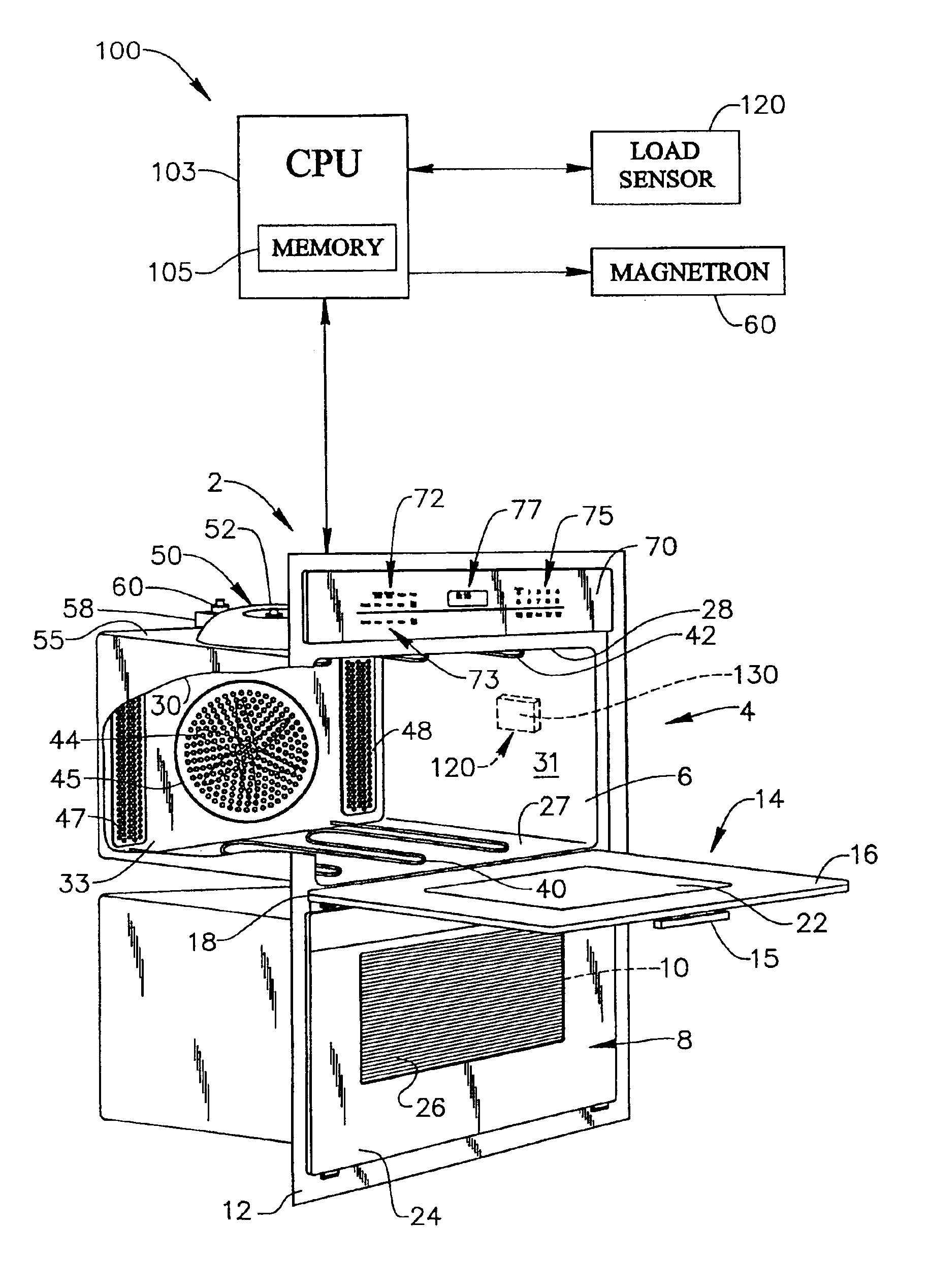
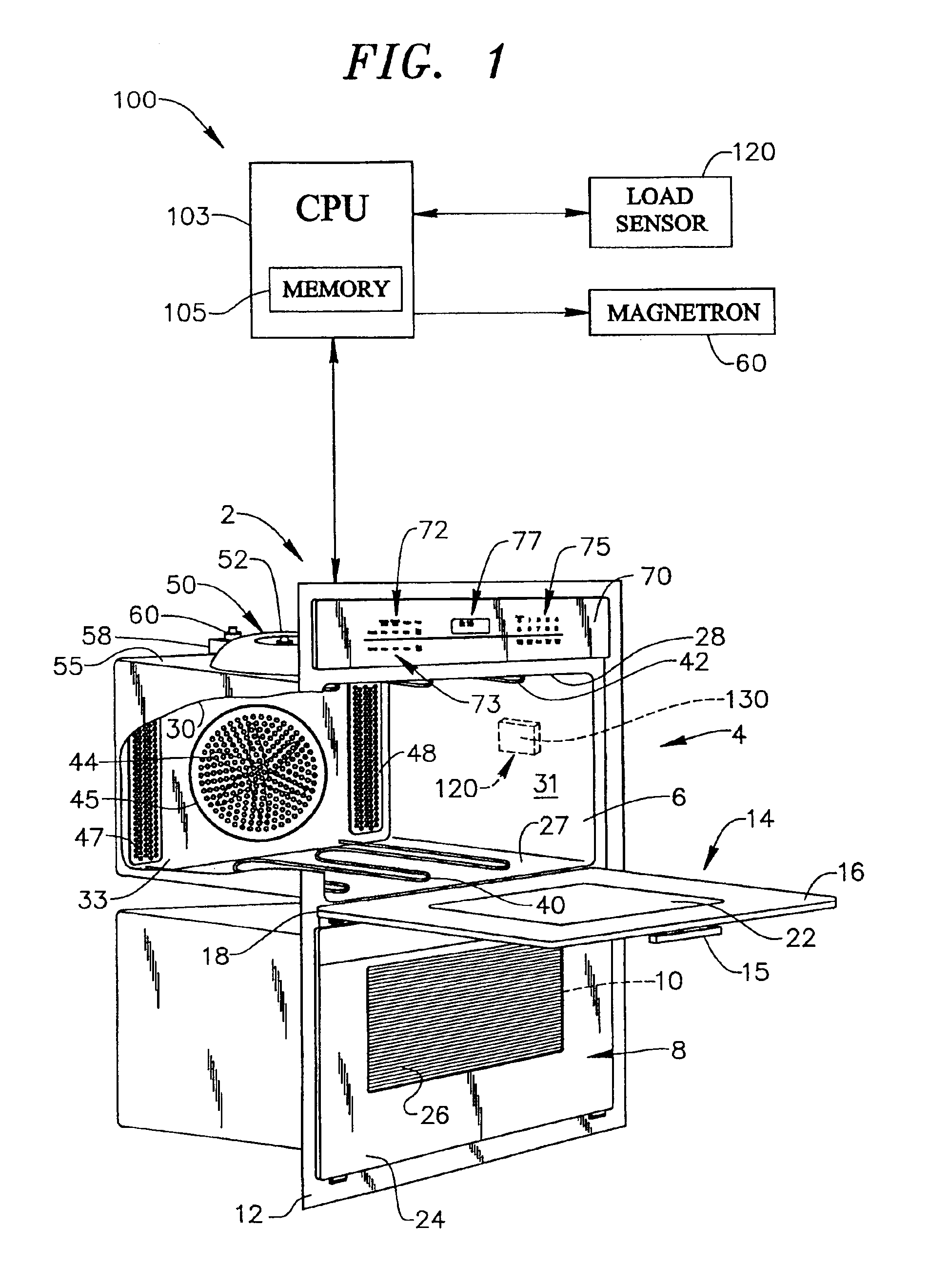
With initial reference to FIG. 1, a cooking appliance constructed in accordance with the present invention is generally indicated at 2. Cooking appliance 2, as depicted, constitutes a double wall oven. However, it should be understood that the present invention is not limited to this model type and may be incorporated into various other types of oven configurations, e.g., cabinet mounted ovens, slide-in and free standing ranges, as well as conventional countertop models. In any event, in the embodiment shown, cooking appliance 2 constitutes a dual oven wall unit including an upper oven 4 having an upper oven cavity 6 and a lower oven 8 having a corresponding lower oven cavity 10. In further accordance with the embodiment shown, cooking appliance 2 includes an outer frame 12 for, at least partially, supporting both upper and lower oven cavities 6 and 10 within a wall or other appropriate structure.

In a manner known in the art, cooking appliance 2 includes a door assembly 14 adapted t...


PUM


Abstract

A microwave cooking appliance includes an oven cavity, a magnetron and a load sensing system. The load sensing system is used to detects the presence of a load in the oven cavity by introducing a high frequency energy burst into the oven cavity, with the energy burst being reflected back. A controller, based on a time period between emitted and reflected signals, determines whether a load is present in the oven cavity. If no load is present, operation of the magnetron is terminated. Preferably, the high frequency energy burst is an ultrasonic acoustic frequency energy burst in a range between approximately 10 kHz and 100 kHz.

Description

BACKGROUND OF THE INVENTION1. Field of the InventionThe present invention pertains to the art of cooking appliances and, more particularly, to a microwave cooking appliance including a system for sensing the presence of a load in an oven cavity of the cooking appliance.2. Discussion of the Prior ArtCooking appliances utilizing a directed microwave energy field to cook a food item have existed for some time. In general, a cooking process is performed operating a microwave emitter, such as a magnetron, to direct standing microwave energy fields into an oven cavity such that the microwave energy fields reflect about the oven cavity and impinge upon the food item. As the microwave energy fields impinge upon the food item, the energy fields are converted into heat through two mechanisms. The first mechanism, ionic heating, results from the liner acceleration of ions, generally in the form of salts, present within the food item. The second mechanism is the molecular excitation of polar mo...

Claims


Application Information

Patent Timeline
Patent Type & Authority Patents(United States)
IPC IPC(8): F24C7/02F24C7/08H05B6/68
CPCH05B6/666H05B2206/043
Inventor SCHULTE, ROBERT A.
Owner ACP OF DELAWARE
Learn More