Stage apparatus which supports interferometer, stage position measurement method, projection exposure apparatus, projection exposure apparatus maintenance method, semiconductor device manufacturing method, and semiconductor manufacturing factory

Inactive Publication Date: 2005-03-15
CANON KK
View PDF9 Cites 13 Cited by
  • Summary
  • Abstract
  • Description
  • Claims
  • Application Information

AI Technical Summary

Benefits of technology

[0015]The present invention has been made to overcome the conventional drawbacks, and has as its object to provide a mov

Problems solved by technology

The optical unit can make the reference and measurement beams interfere with each other.
Alter

Method used


Image

  • Stage apparatus which supports interferometer, stage position measurement method, projection exposure apparatus, projection exposure apparatus maintenance method, semiconductor device manufacturing method, and semiconductor manufacturing factory
  • Stage apparatus which supports interferometer, stage position measurement method, projection exposure apparatus, projection exposure apparatus maintenance method, semiconductor device manufacturing method, and semiconductor manufacturing factory
  • Stage apparatus which supports interferometer, stage position measurement method, projection exposure apparatus, projection exposure apparatus maintenance method, semiconductor device manufacturing method, and semiconductor manufacturing factory

Examples


first embodiment

[0044](First Embodiment)

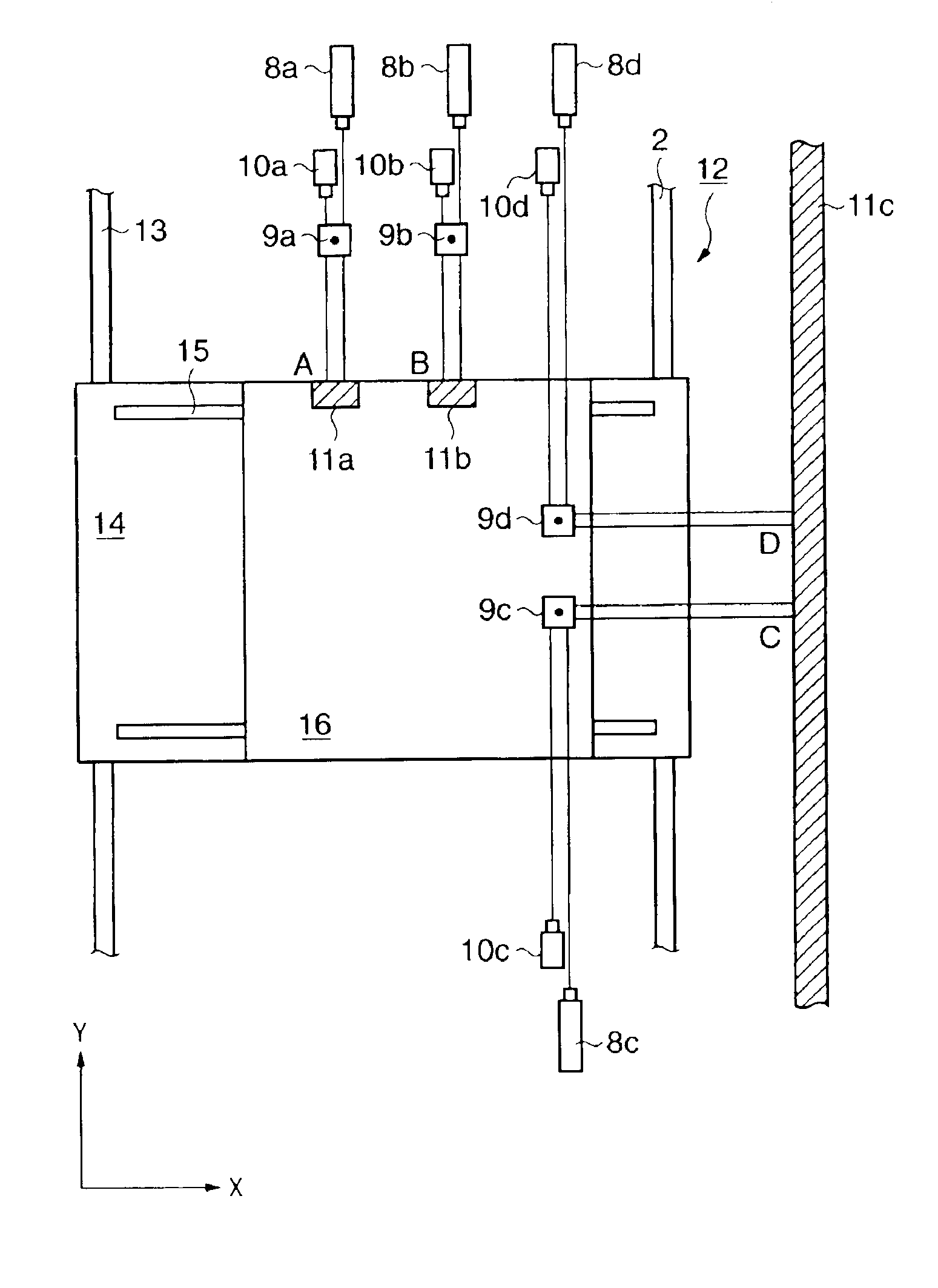
[0045]FIG. 1 shows a stage apparatus which is a triaxial stage having X-, Y-, and θ-axes with a degree of freedom in the plane direction. In this stage apparatus, the stroke is long along the Y-axis, and short along the θ-axis and the X-axis perpendicular to the Y-axis. The bar mirror of a laser interferometer for measuring the long-stroke axis (Y-axis) is mounted on a stage movable portion, and its optical unit and detector are arranged outside the stage movable portion. The optical unit of a laser interferometer for measuring the short-stroke axes (X- and θ-axis) is mounted on a stage movable portion, and its bar mirror and detector are arranged outside the stage movable portion.

[0046]In FIG. 1, a reticle stage 1 is supported on a guide 2 in a non-contact manner by a hydrostatic bearing (not shown) so as to be movable along the three, X-, Y-, and θ-axes. The reticle stage 1 supports a reticle (not shown), and is driven by linear motors 3 serving as a drivin...

second embodiment

[0065](Second Embodiment)

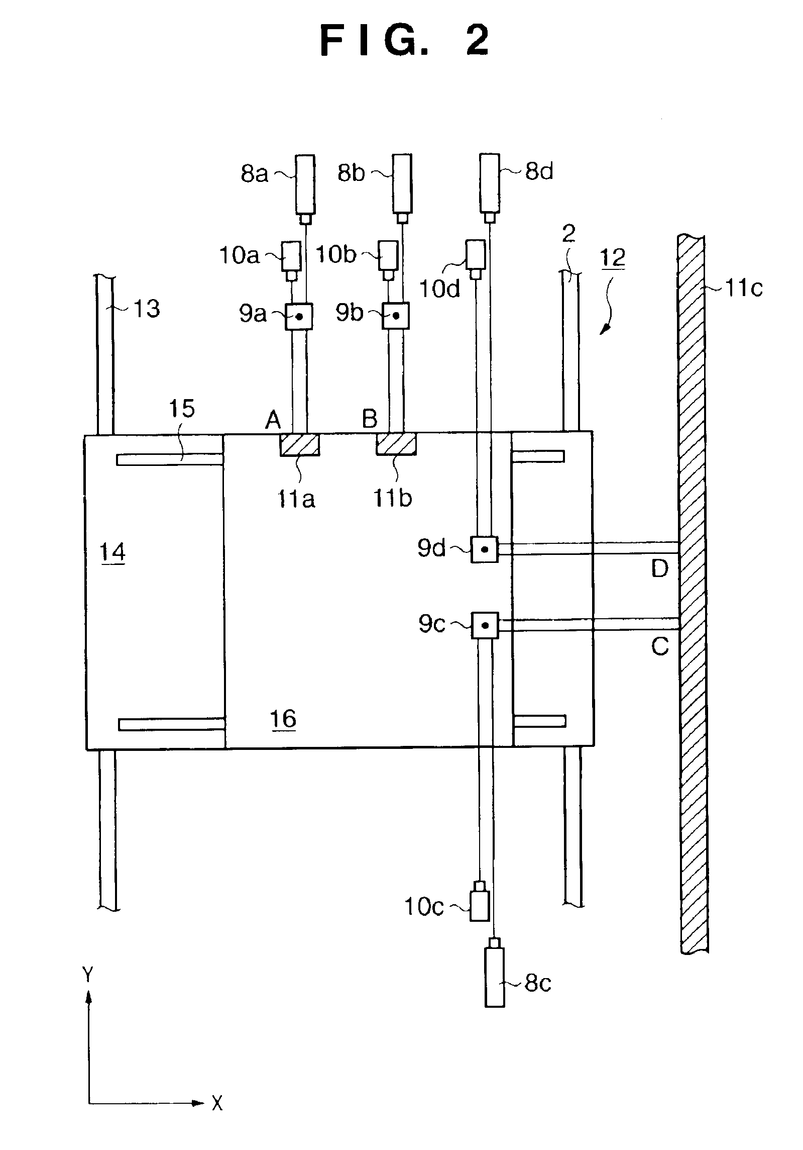
[0066]FIG. 2 shows an interferometer-mounted stage according to the second embodiment.

[0067]In the first embodiment, the stage 1 has a one-plate structure, is supported on the guide 2 in three axial directions, and is movable in the three axial directions. In the second embodiment, a stage has a stacked structure, and is mounted on a Y stage which moves with a long stroke along the Y-axis. The stage is movable with a short stroke in the X and θ directions on the Y stage. That is, the stage is movable in the three axial directions including Y-axis movement of the Y stage.

[0068]FIG. 2 shows an interferometer-mounted stage which is a triaxial stage having X-, Y-, and θ-axes with a degree of freedom in the plane direction. In this stage, the stroke is long along the Y-axis, and short along the θ-axis and the X-axis perpendicular to the Y-axis. The bar mirror of a laser interferometer for measuring the long-stroke axis (Y-axis) is mounted on a stage movable porti...

third embodiment

[0087](Third Embodiment)

[0088]FIGS. 3A and 3B show an interferometer-mounted stage having six degrees of freedom. In this stage, the stroke is long along the Y-axis, and short along the X- and Z-axes. The bar mirror of a laser interferometer for measuring the long-stroke axis (Y-axis) is mounted on a stage movable portion, and its optical unit and detector are arranged outside the stage movable portion. The optical unit of a laser interferometer for measuring the short-stroke axes (X- and Z-axis) is mounted on a stage movable portion, and its bar mirror and detector are arranged outside the stage movable portion.

[0089]As shown in FIG. 3A, the long-stroke axis (Y-axis) is measured by the bar mirror mounted on the stage movable portion and the optical unit and detector arranged outside the stage movable portion. Another optical unit is mounted on the stage movable portion, and the short-stroke axis (X-axis) is measured by the bar mirror and detector arranged outside the stage movable ...


PUM


Abstract

A stage apparatus includes a stage movable along at least one axis, a laser head for generating a laser beam, an optical unit which is mounted on the stage and splits the laser beam into reference and measurement beams, a mirror which is arranged outside the stage and reflects the measurement beam, and a detector which is arranged outside the stage and detects an interference beam of the reference and measurement beams.

Description

FIELD OF THE INVENTION[0002]The present invention relates to a stage apparatus which supports an interferometer for measuring the position of a stage movable in at least one axial direction by using a laser interferometer and, more particularly, to a stage apparatus which supports an interferometer for measuring the position of a stage having long and short stroke axes by using a laser interferometer. Also, the present invention relates to a projection exposure apparatus having this stage as a reticle stage and / or wafer stage, and a method of manufacturing a semiconductor device or the like by using the projection exposure apparatus.BACKGROUND OF THE INVENTION[0003]Conventionally, in the technical field which requires high-precision processing, various processing operations are done by setting an object to be processed on a stage which can be aligned at high precision, and controlling the stage. The prior art will be described by exemplifying a projection exposure apparatus used in ...

Claims


Application Information

Patent Timeline
IPC IPC(8): G03F7/20H01L21/027G01B11/00
CPCG03F7/708G03F7/70691
Inventor IWAMOTO, KAZUNORIASANO, TOSHIYA
Owner CANON KK
Why Eureka
Try Eureka