Image forming apparatus with reduced variation of rotation speed of image carrier

a technology of rotating speed and image carrier, which is applied in the field of image forming apparatus, can solve the problems of color misregister in the full-color image, eccentricity of the drum shaft or the drive shaft, and cumulative tooth pitch error of the driven gear, so as to reduce the speed variation of the image carrier and reduce the misregister

Inactive Publication Date: 2005-03-15
RICOH KK
View PDF24 Cites 27 Cited by
  • Summary
  • Abstract
  • Description
  • Claims
  • Application Information

AI Technical Summary

Benefits of technology

It is a first object of the present invention to provide an image forming apparatus capable of reducing the speed variation of an image

Problems solved by technology

When such a drive system is used for accurate drum drive, it is likely that the speed variation of the individual drum brings about the misregister of pixel positions transferred to the sheet, belt or similar transfer medium, resulting in the misregister of colors in the full-color image.
The major causes of the drum speed variation are (1) the variation of rotation speed of each gear or similar drive transmission member included in a drive transmission system between the drive motor and the driven member of the drum shaft, and (2) the eccentricity of the drum shaft or that of the driven gear as well as the cumulative tooth pitch error of the driven gear.
However, when it comes to the drum speed variation ascribable to the cause (2), the method described above cannot satisfy a condition that makes the parameter fi/fo or τ/T an integer.
It is therefore difficult to obviate the misregister of colors ascribable to the drum speed variation.
However, although the flywheel may reduce high-frequency oscillation ascribable to, e.g., gears, it cannot easily reduce drum speed variation ascribable to the eccentricity of gears constituting the drive transmission system.
As a result, the rigidity of the drive transmission system is lowered to make accurate control difficult to execute.
However, because consideration is not given to the influence of a difference in phase between the speed varia

Method used


Image

  • Image forming apparatus with reduced variation of rotation speed of image carrier
  • Image forming apparatus with reduced variation of rotation speed of image carrier
  • Image forming apparatus with reduced variation of rotation speed of image carrier

Examples


first embodiment

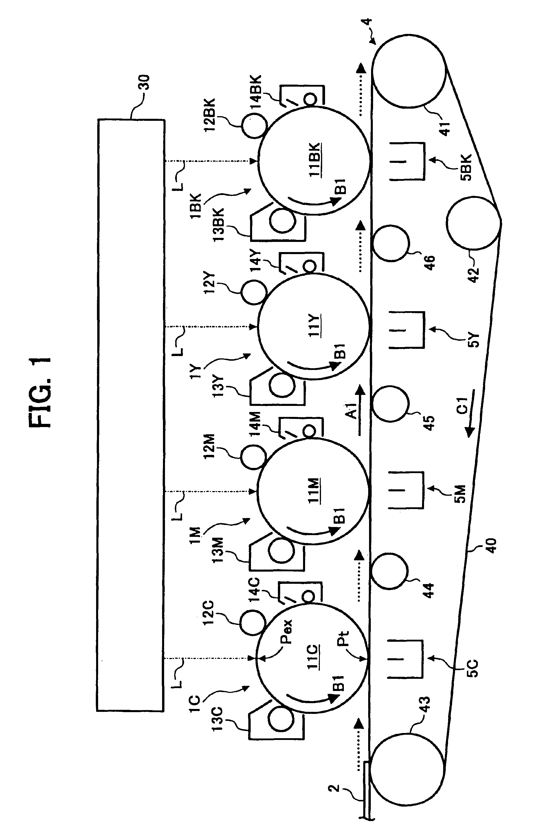
Referring to FIG. 1 of the drawings, a tandem color printer includes four toner image forming sections 1Y (yellow), 1M (magenta), 1C (cyan) and 1BK (black) for forming images with yellow toner, magenta toner, cyan toner and black toner, respectively. The image forming sections 1Y through 1BK are sequentially arranged from the upstream side toward the downstream side in a direction A in which a sheet or transfer medium (recording medium) 2 is conveyed. The image forming section 1Y includes a photoconductive drum or image carrier 11Y rotatable in a direction B1, a charge roller 12Y for uniformly charging the surface of the drum 11Y, a developing unit 13Y for developing a latent image formed on the drum 11Y, and a drum cleaning unit 14Y for cleaning the drum 11Y after the transfer of a toner image to the sheet 2.

The other image forming sections 1M, 1C and 1BK are identical in configuration with the image forming section 1Y except for the color of toner to use; identical structural elem...

second embodiment

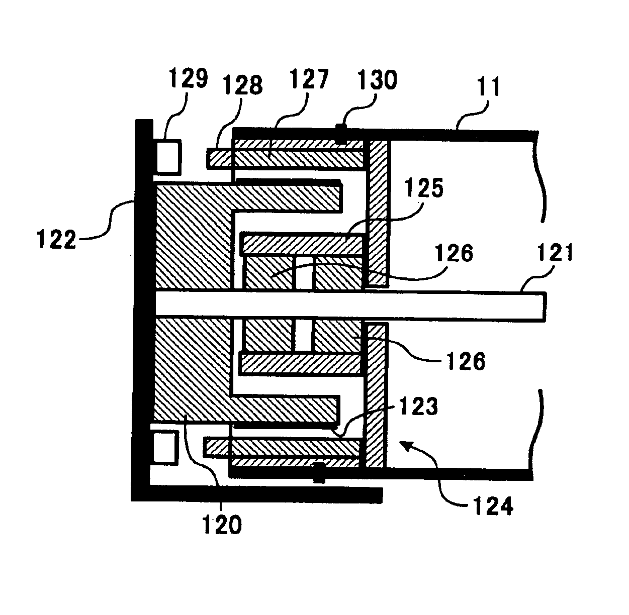
A second embodiment is identical with the first embodiment except for the drum drive unit. The second embodiment does not reduce the rotation speed variation of the driven gear itself, but matches the phases of the rotation speed variations of the driven gears ascribable to, e.g., eccentricity. FIG. 9 shows the drum drive unit of the illustrative embodiment and indicates the principle of phase matching unique to the illustrative embodiment. Before the drum drive unit is mounted to the printer body, adjustment is effected with an encoder of the type sensing an absolute angle mounted in place of the drum.

As shown in FIG. 9, the drum drive unit includes a drive motor 101A assigned to the BK drum and a drive motor 101B shared by the M, C and Y drums. A driven gear member 103C associated with the C drum 11C (C drive gear 103C hereinafter) transmits the rotation of the drive motor 101B to a driven gear 103M associated with the M drum 11M (M driven gear 103M hereinafter) via an idler 115. ...

third embodiment

A third embodiment is identical with the first embodiment except for the drum drive unit. The third embodiment differs from the first and second embodiments in that it causes the drive motors to directly drive the drums without the intermediary of the driven gears.

It is a common practice with a direct drive system to reduce the rotation speed of a drive motor by using a drive transmission mechanism, e.g., gears. For example, Japanese Patent Laid-Open Publication No. 10-63059 mentioned earlier teaches a large flywheel mounted on the shaft of a photoconductive drum in order to reduce high-frequency oscillation particular to the drive transmission mechanism. While this kind of system enhances motor efficiency, gears, for example, included in the drive transmission mechanism cause the rigidity of the mechanism to decrease and bring about rotation speed variations ascribable to, e.g., the eccentricity of the gears. This makes it difficult to effect constant rotation control with accuracy...


PUM


Abstract

An image forming apparatus that reduces an influence of the variation of rotation speed of an image carrier, which is ascribable to, e.g., the eccentricity of a driven transmission member mounted on the image carrier, on the misregister of different colors. Further, the apparatus reduces the influence of the load variation of the image carrier acting on a transfer medium drive member on the misregister of different colors.

Description

BACKGROUND OF THE INVENTION1. Field of the InventionThe present invention relates to a copier, printer, facsimile apparatus or similar image forming apparatus. More particularly, the present invention relates to an image forming apparatus capable of reducing the influence of the variation of rotation speed of an image carrier, which is ascribable to, e.g., the eccentricity of a driven transmission member mounted on the image carrier, on the misregister of different colors as well as the influence of the load variation of the image carrier acting on transfer medium drive means on the misregister of different colors.2. Description of the Background ArtToday, to meet the increasing demand for color copies and color prints, an ink jet image forming apparatus is predominant in a low-speed range while an electrophotographic image forming apparatus is predominant in a medium- and a high-speed range. Particularly, a tandem color image forming apparatus including a plurality of photoconducti...

Claims


Application Information

Patent Timeline
IPC IPC(8): G03G15/00G03G15/01
CPCG03G15/757G03G15/0194G03G2215/0119G03G2215/0158G03G2215/0141
Inventor KOIDE, HIROSHI
Owner RICOH KK
Why Eureka
Try Eureka