Manufacturing method for multi-layered body, manufacturing equipment for same, and multi-layered body

a manufacturing method and multi-layer technology, applied in the field of multi-layer body, can solve the problems of disrupting the cross section of the lamination, the inability to form uniform layers, and so as to reduce the thickness variation among the layers or the disruption of the lengthwise arrangement, prevent the disappearance of layers, and increase the resistance to the disruption of the lamination.

Active Publication Date: 2013-03-14
KURARAY CO LTD
View PDF6 Cites 0 Cited by
  • Summary
  • Abstract
  • Description
  • Claims
  • Application Information

AI Technical Summary

Benefits of technology

[0098]According to the present invention, the local flow speed variations, which occur in a flow path for forming a multi-laminated body, are reduced, and thus increasing the resistance to the disruption in the lamination. As a result, it is possible to prevent the disappearance of layers at both ends and to reduce the thickness variations among the layers or the disruption in the lengthwise arrangement. In addition, it is possible to form uniform layers while preventing the reduction in the thickness of the layers at both ends.

Problems solved by technology

However, since the manufacturing methods according to Patent literatures 1 and 2 form lamination layers in which the layers are oriented in a lateral direction, there is a problem that thickness variations among layers occur, and thus making it impossible to form uniform layers.
Therefore, there is a problem that layers at the left / right ends of an obtained lengthwise-oriented article could disappear as the number of times of the divisions and the arrangements increases, and thus causing thickness variations among the layers and disruptions in the lengthwise arrangement.
As a result, every time the division, the branching, the rearrangement, and the recombining are repeated, the effect of the variations becomes larger, and thus causing a problem that the cross section of the lamination is disrupted and the layers are vertically lowered.
Therefore, there is a problem that eventually the rate of the defective part increases so much that the performance of the apparatus is adversely affected.

Method used


Image

  • Manufacturing method for multi-layered body, manufacturing equipment for same, and multi-layered body
  • Manufacturing method for multi-layered body, manufacturing equipment for same, and multi-layered body
  • Manufacturing method for multi-layered body, manufacturing equipment for same, and multi-layered body

Examples


first exemplary embodiment

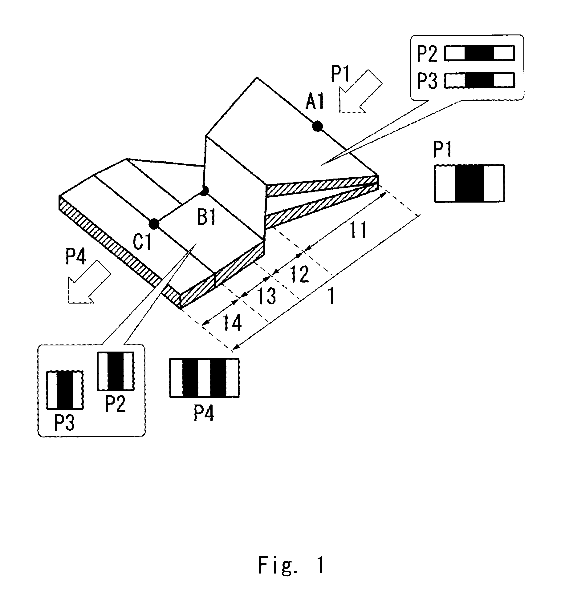
[0112]A method for manufacturing a multi-laminated body according to a first exemplary embodiment of the present invention is explained hereinafter.

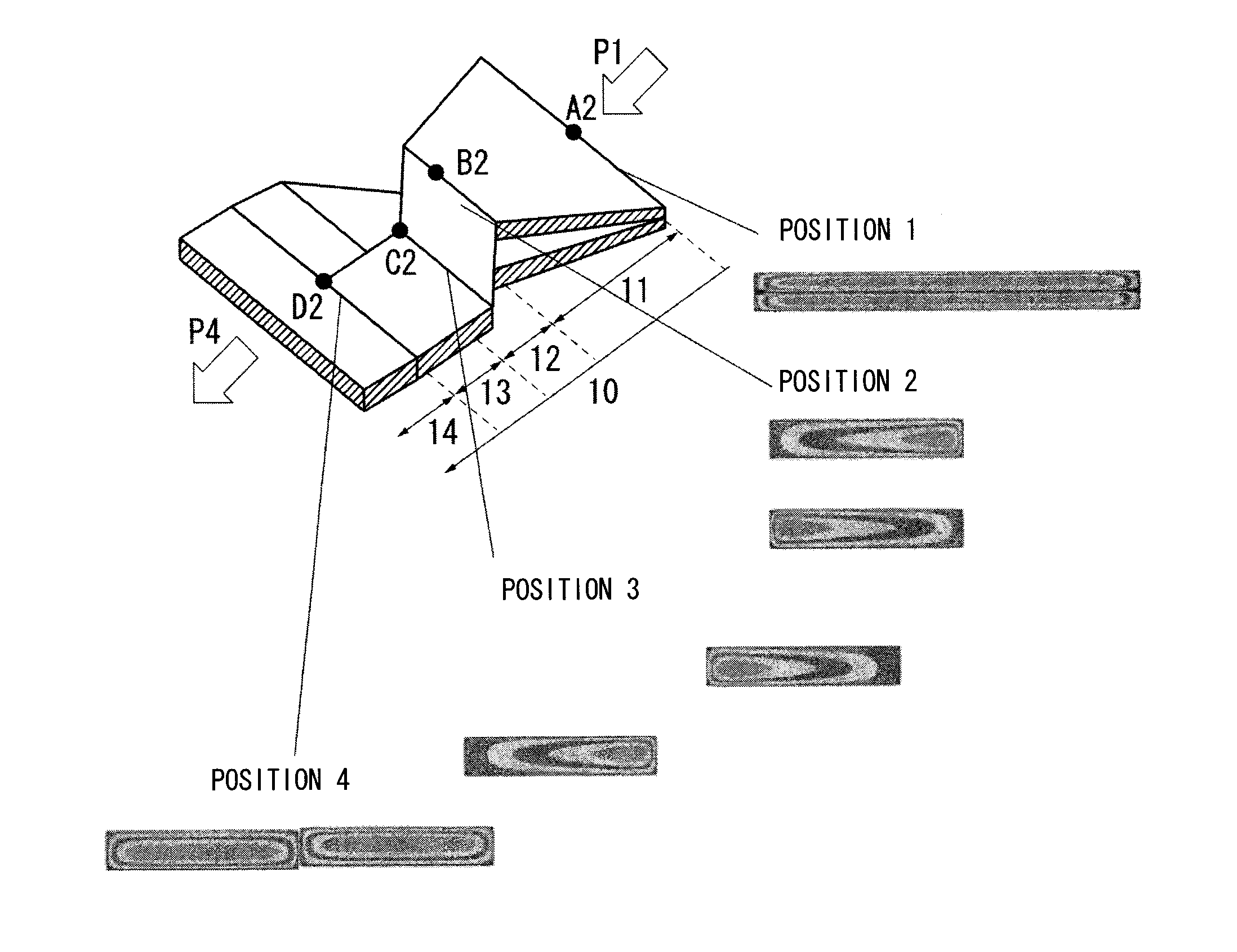
[0113]The inventors of the present invention have diligently examined for a multi-laminated body capable of reducing the flow speed variations and reducing the thickness variations among the layers or the disruption in the lengthwise arrangement. In particular, the inventors have confirmed that the mechanism for arranging layers affects the stability of the layer structure. Therefore, the inventors have paid attention to the fact that in an arrangement in the same direction, layers at both ends disappear as the number of divisions increases and the shape of the middle layer is thereby disrupted, and have examined again and again for a multi-laminated body in which the thickness variations among the layers, the disruption in the arrangement, and the disappearance of layers at both ends do not occur.

[0114]As a result, the inventors have fo...

second exemplary embodiment

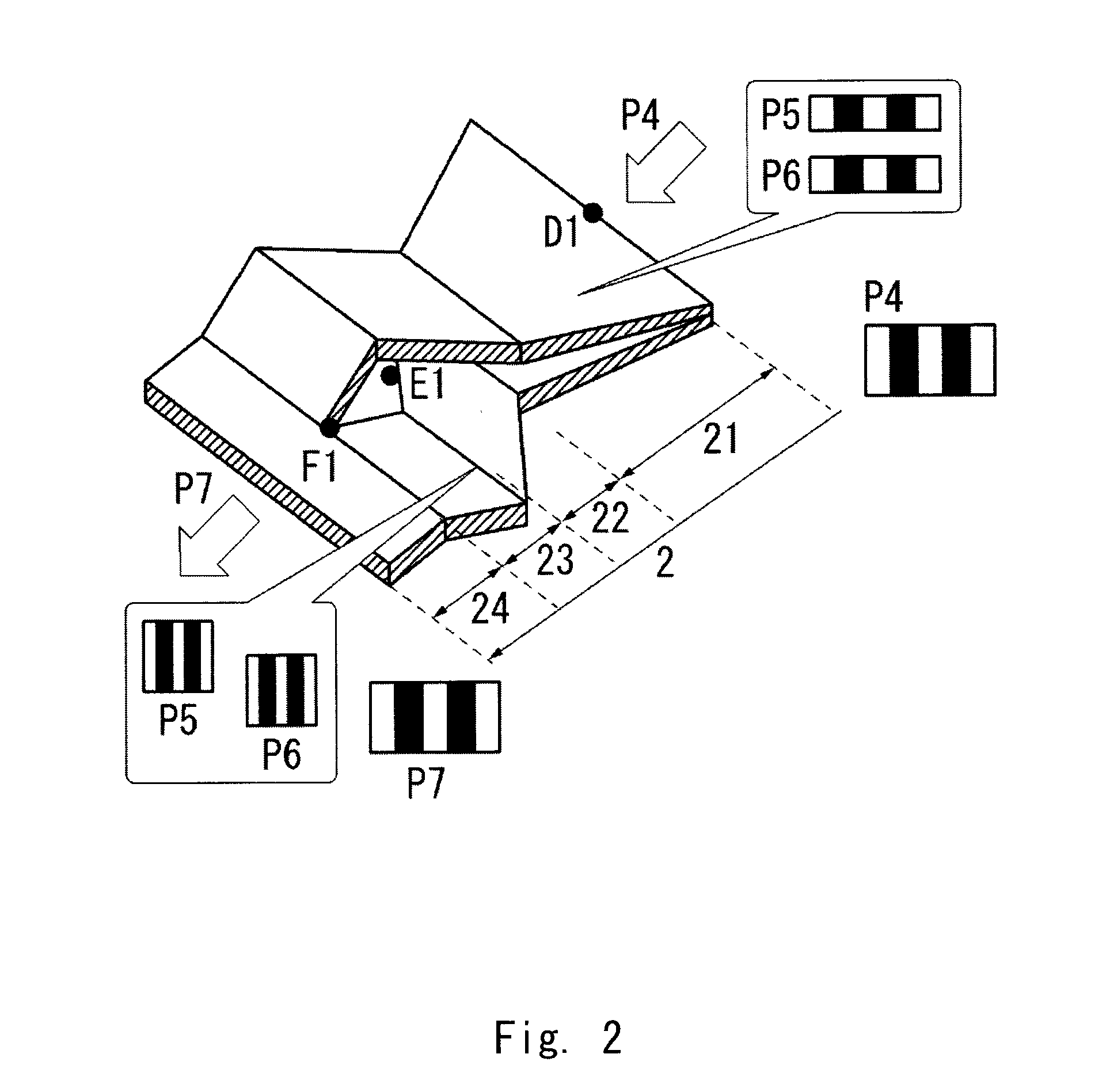
[0141]A method for manufacturing a multi-laminated body according to a second exemplary embodiment of the present invention is explained hereinafter.

[0142]The inventors of the present invention have diligently examined for a multi-laminated body capable of reducing the flow speed variations, increasing the resistance to the disruption in the lamination, and reducing the inclination of layers. In particular, the inventors have paid attention to the fact that the resin flow speed is high and layers are thereby inclined at an arrangement section having a short flow path and a sharp curve, and have examined again and again the effect to the improvement in the layer verticality resulting from the increase in the length of the flow path in the arrangement section located behind the division section that is lengthened in order to smooth the flow of the laminated flow within the flow path. As a result, the inventors have found that the long flow path arrangement can dramatically improve the...

example 1-1

[0194]As the resin material used for a multi-laminated body, polymethyl methacrylate (PMMA, Parapet GF: Kuraray Co., Ltd.) and ultramarine polymethyl methacrylate (PMMA, Parapet GF: Kuraray Co., Ltd.) were used as a resin A and a resin B respectively. After the resins A and B were dried at 80° C. for a whole day and night, they were supplied to an extrusion machine (PSV-type 22 mm: PULAENG Company Ltd.).

[0195]Each of the resins A and B was brought into a molten state at 235° C. in the extrusion machine (PSV-type 22 mm: PULAENG Company Ltd.) and was supplied through a laminated flow inlet into a multi-lamination extrusion molding machine using a die (plate) in which an L-flow path for which L2 / L1=0.58 and an R-flow path for which L2 / L1=0.58 were alternately arranged, i.e., combined in the order of “L-flow path / R-flow path / L-flow path” while measuring the amounts of the resins A and B by using a gear pump so that the discharge ratio becomes “resin A / resin B=1 / 1”.

[0196]In this way, a l...


PUM

PropertyMeasurementUnit
bending angleaaaaaaaaaa
lengthaaaaaaaaaa
widthaaaaaaaaaa

Abstract

A manufacturing method of a multi-laminated body according to the present invention includes a step 1 (L-flow path) for vertically dividing a laminated flow obtained by arranging at least two molten resins adjacent to each other in a lengthwise direction into two sections, guiding the divided laminated flows to opposite directions relative to the flow direction, and then guiding both laminated flows toward the center of the flow direction, and rearranging the laminated flows adjacent to each other in the horizontal direction and thereby joining the laminated flows together, and a step 2 (R-flow path) for vertically dividing a laminated flow obtained by arranging at least two molten resins adjacent to each other in a lengthwise direction into two sections, guiding the divided laminated flows to directions opposite to the above-mentioned directions relative to the flow direction, and then guiding both laminated flows toward the center of the flow direction, and rearranging the laminated flows adjacent to each other in the horizontal direction and thereby joining the laminated flows together, in which the step 1 (L-flow path) and the step 1 (R-flow path) are alternately repeated in this listed order, and a number of the steps to be performed is at least three. According to this method, it is possible to prevent the layer disappearance at both ends, prevent the layer thickness variations or the disruption in the lengthwise arrangement, and thereby manufacture a multi-laminated body having a more excellent uniformity.

Description

TECHNICAL FIELD[0001]The present invention relates to a multi-laminated body composed of a high polymer material(s) having a melt-fluidity and a hardening ability, its manufacturing method, and its manufacturing apparatus.BACKGROUND ART[0002]In recent years, developments to uses for high-functionality films for packaging and other films for the purpose of improving the barrier property, especially for optical films using optical control such as a polarizing-plate protection film of a liquid crystal display device and an optical compensation film has been in progress.[0003]For example, by alternately laminating a layer having a high refractivity and a layer having a low refractivity a number of times, an optical interference film that selectively reflects light having a specific wavelength or lets the light pass therethrough by the interference of the light between these layers is obtained. By adjusting the wavelength range of the light that is selectively reflected or let pass throu...

Claims


Application Information

Patent Timeline
Patent Type & Authority Applications(United States)
IPC IPC(8): B29C47/06B29C48/08B29C48/30B29C48/305B29C48/495B29C48/71B29C48/92
CPCB29C47/065B29L2007/008B29L2009/00B29L2011/00Y10T428/24174B29C48/21B29C48/19B29C48/71B29C48/07B29C48/08B29C48/70B29C48/304B29C48/307B29C48/695B29C2948/926B29C2948/92104B29C2948/92152B29C2948/92171B29C2948/92447B29C2948/92904B29C48/495
Inventor KANAI, SHIMONZENTO, TOSHIYUKITOMIYAMA, KOHTANAKATA, HIROMICHI
Owner KURARAY CO LTD
Why Eureka
Try Eureka