
Repeater with diversity transmission

a technology of transmission frequency and transmission frequency, applied in the direction of radio transmission, active radio relay system, electrical apparatus, etc., can solve the problem that and the power of the received signal is typically larg

Inactive Publication Date: 2005-03-15
QUALCOMM INC
View PDF6 Cites 33 Cited by
  • Summary
  • Abstract
  • Description
  • Claims
  • Application Information

AI Technical Summary

Benefits of technology

It is an object of some aspects of the present invention to provide an improved method and apparatus for repeating of electromagnetic signals.
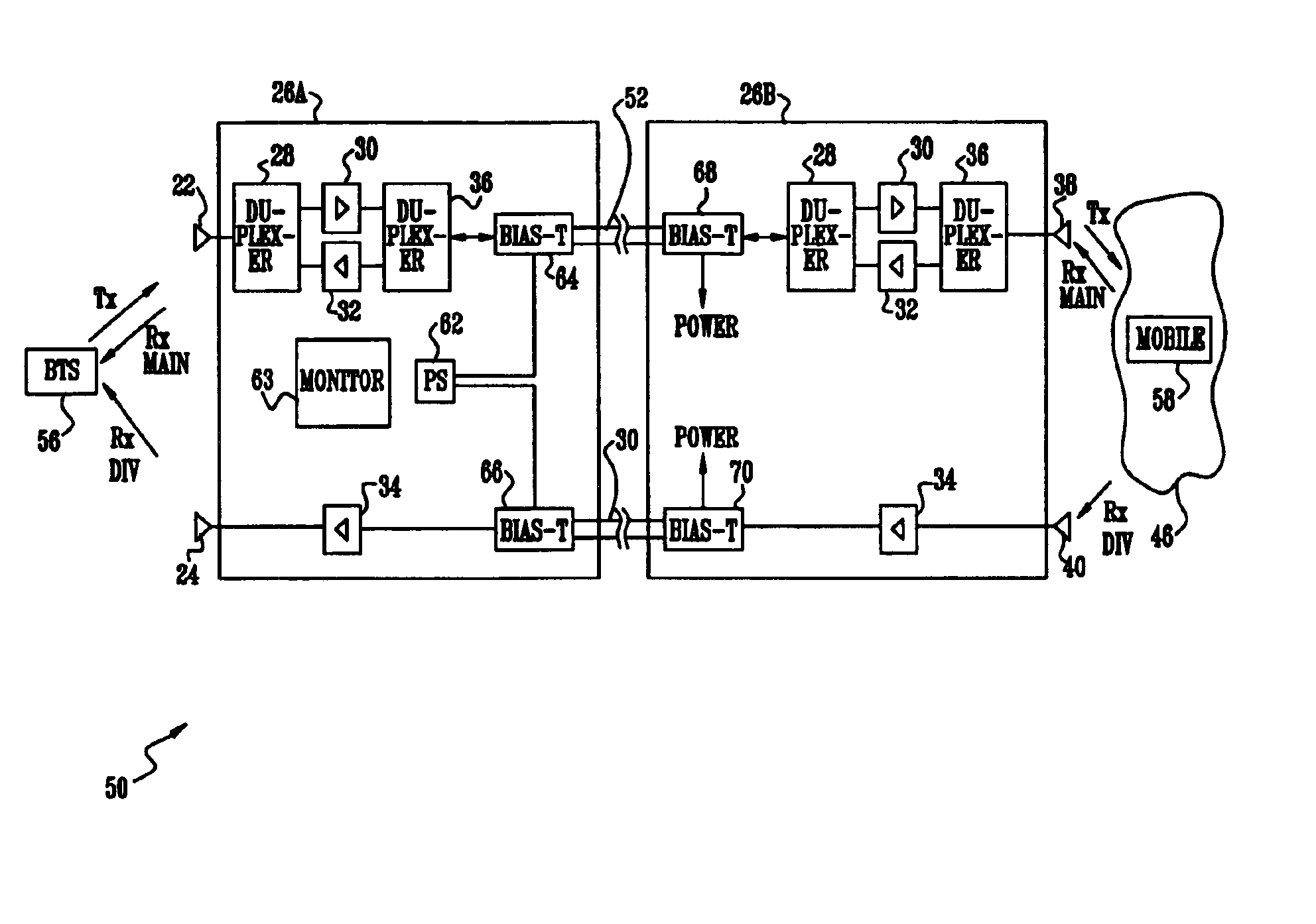
In some preferred embodiments of the present invention, the repeater system comprises two separate repeater units which together operate substantially as described above. One of the units communicates with the BTS, and the other unit communicates with the mobile. The separate units are coupled by cabling which transfers signals between the units. Implementing the repeater system as coupled units allows each of the units to be positioned relatively independently, increasing the flexibility of use of the repeater system.
In some preferred embodiments comprising two separate repeater units, frequency conversion is performed within the separate units. The converted frequencies are preferably intermediate frequencies having a substantially lower frequency than initial signals broadcast by the BTS and the mobile. The intermediate frequencies are transferred by cabling which comprises cables adapted to transfer electric signals, and the initial signals, comprising forward, reverse-main and reverse-diversity signals, are recovered after the transfer. Alternatively, at least some of the frequency conversion is implemented by modulating an optical carrier with one or more of the initial signals. Thus, the converted frequencies comprise optical radiation, and the cabling comprises a fiber optic guide. Implementing frequency conversion in the separate units reduces losses generated within the cabling coupling the units, so that the units may be separated by significantly larger distances compared to units where there is no frequency conversion. Separation of the units also enables output radio-frequency (RF) units to be positioned close to their respective antennas, so reducing the required output from each RF output unit.

Problems solved by technology

Cellular communications receivers typically suffer from large variations in received signal power, due to phenomena such as Rayleigh and Ricean fading.

Method used


Image

  • Repeater with diversity transmission
  • Repeater with diversity transmission
  • Repeater with diversity transmission

Examples


Embodiment Construction

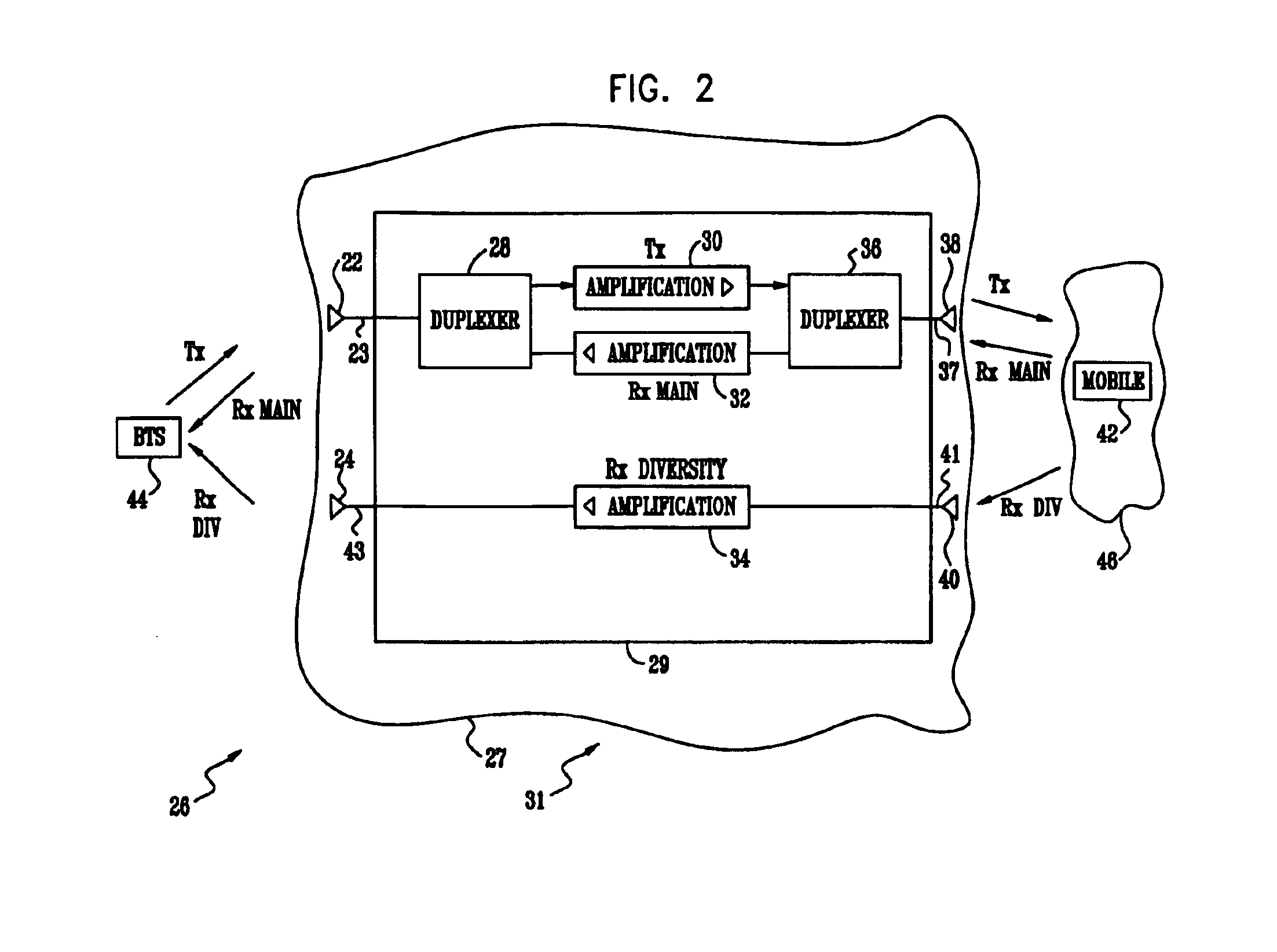
Reference is now made to FIG. 2, which schematically illustrates a combined main / diversity repeater 26, according to a preferred embodiment of the present invention. Repeater 26 operates in a cellular communications network 31, and is implemented so as transfer signals between a region 27, wherein the repeater is located, and a region 46 remote from region 27. Repeater 26 is also implemented so as to transfer signals between itself and a base-station transceiver system (BTS) 44 remote from the repeater. Network 29 preferably operates according to a code division multiple access (CDMA) protocol, and in the description below network 29 is assumed, by way of example, to operate as a CDMA personal communication systems (PCS) network in a band from approximately 1850 MHz-1990 MHz. It will be understood, however, that the principles of the present invention apply to cellular communications networks operating under other protocols and / or in other frequency bands.

Repeater 26 comprises an an...


PUM


Abstract

A radio-frequency (RF) repeater, including a first repeating section which is adapted to receive and amplify forward-signals from a first transceiver so as to generate amplified-forward-signals and to radiate the amplified-forward-signals to a second transceiver. The first section also receives and amplifies reverse-main-signals from the second transceiver so as to generate amplified-reverse-main-signals and transmits the amplified-reverse-main-signals to the first transceiver. The repeater includes a second repeating section which is adapted to receive and amplify reverse-diversity-signals from the second transceiver so as to generate amplified-reverse-diversity-signals and transmits the amplified-reverse-diversity-signals to the first transceiver.

Description

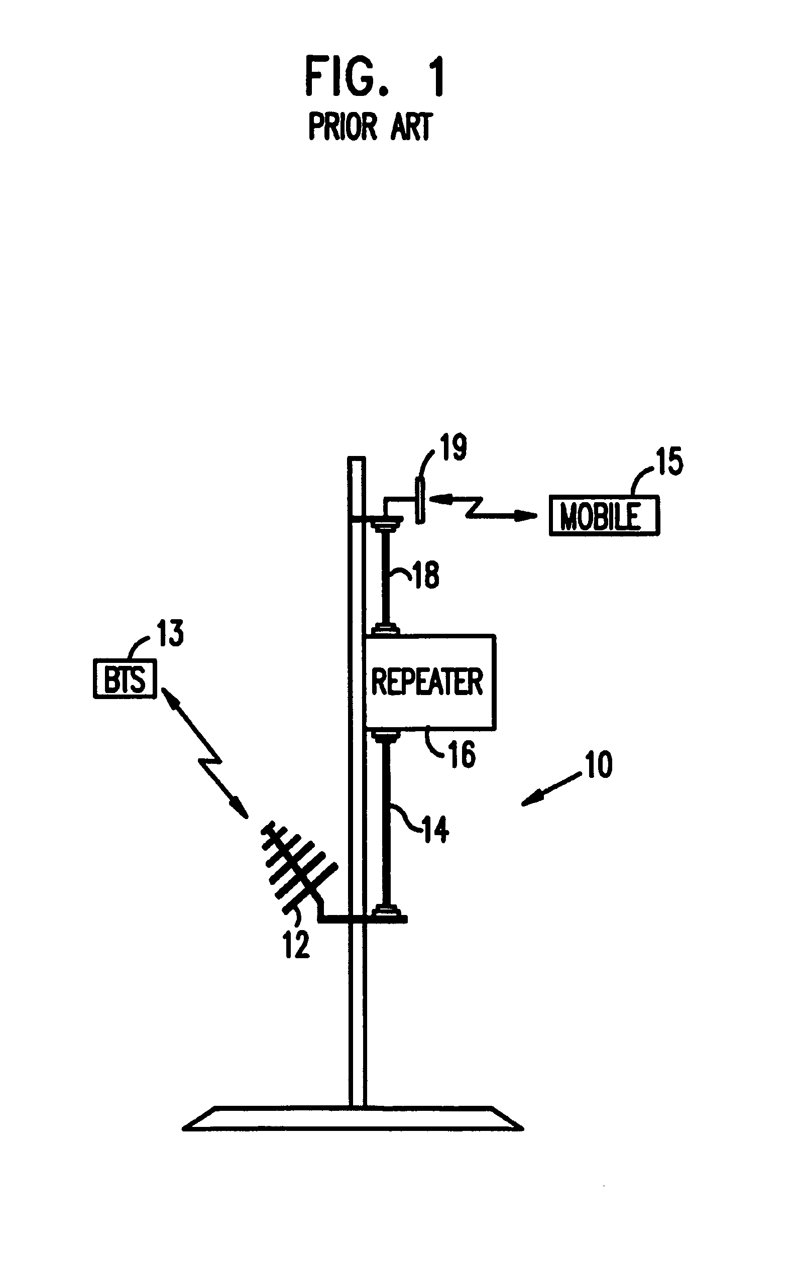
FIELD OF THE INVENTIONThe present invention relates generally to transmission of electromagnetic signals, and specifically to automatic amplification and retransmission of the signals.BACKGROUND OF THE INVENTIONElectronic repeaters, wherein a received electromagnetic signal is automatically amplified and then retransmitted, are well known in the art. Use of a repeater enables a relatively low-power original signal, such as that from a mobile telephone unit, to be transmitted with a power orders of magnitude greater than the original signal.FIG. 1 illustrates a repeater system 10, as is known in the art. A first antenna 12 receives a signal from a first transmitter 13, for example a cellular base-station transceiver system (BTS). The signal is transferred on a coaxial cable 14 to a repeater 16, wherein the signal is amplified and transferred on a coaxial cable 18 to a second antenna 19, which transmits the “repeated” signal generated by repeater 16. Similarly, a signal received by an...

Claims


Application Information

Patent Timeline
IPC IPC(8): H04B7/26H04B7/155
CPCH04B7/2606H04B7/15535
Inventor WEISSMAN, HAIM
Owner QUALCOMM INC
Learn More