Transmitter method, apparatus, and frequency plan for minimizing spurious energy

a technology of spurious energy and transmitters, applied in the field of transmitters, to achieve the effect of reducing noise, reducing noise, and reducing nois

Inactive Publication Date: 2005-03-15
AVAGO TECH WIRELESS IP SINGAPORE PTE
View PDF11 Cites 19 Cited by
  • Summary
  • Abstract
  • Description
  • Claims
  • Application Information

AI Technical Summary

Benefits of technology

Second, the frequency plan causes the offset mixer to generate any off-channel spur(s) at a spur frequency that is separated from the desired IF signal frequency by a significant amount. Since the spur frequency is separated from the desired IF frequency by such an amount, a practically realizable filter after the offset mixer can substantially attenuate the off-channel spur.
The transmitter includes an LO generator having a source oscillator for generating a source LO signal. The LO generator derives the LO signal applied to the offset mixer from the source LO signal. According to the frequency plan, the source LO signal has a relatively high frequency, on the order of 4 GigaHertz (GHz), as compared

Problems solved by technology

First, the frequency plan causes the offset mixer to generate any on-channel spurs at a spur power level that is significantly lower than the desired IF signal power level generated by the m

Method used


Image

  • Transmitter method, apparatus, and frequency plan for minimizing spurious energy
  • Transmitter method, apparatus, and frequency plan for minimizing spurious energy
  • Transmitter method, apparatus, and frequency plan for minimizing spurious energy

Examples


Embodiment Construction

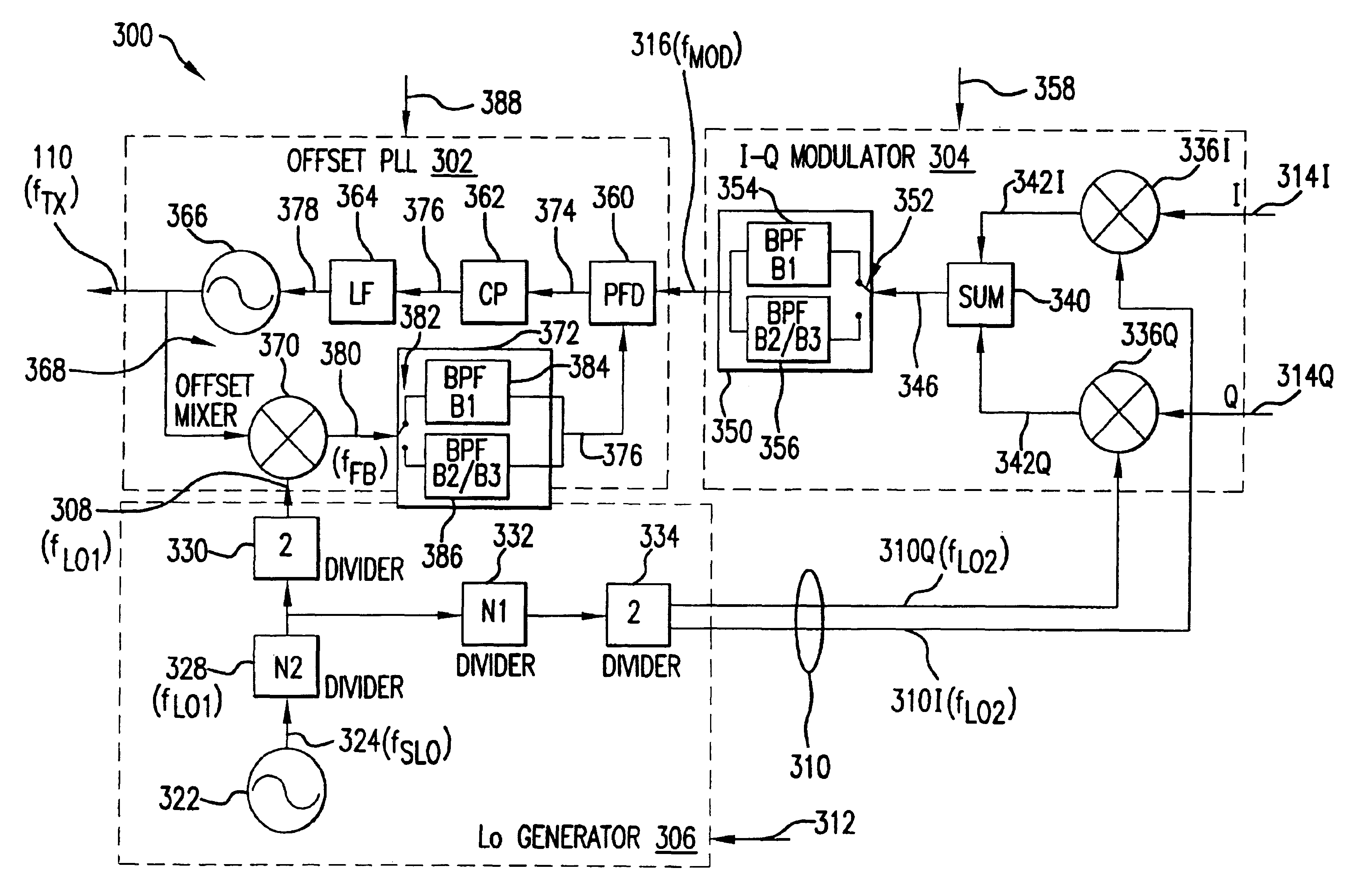
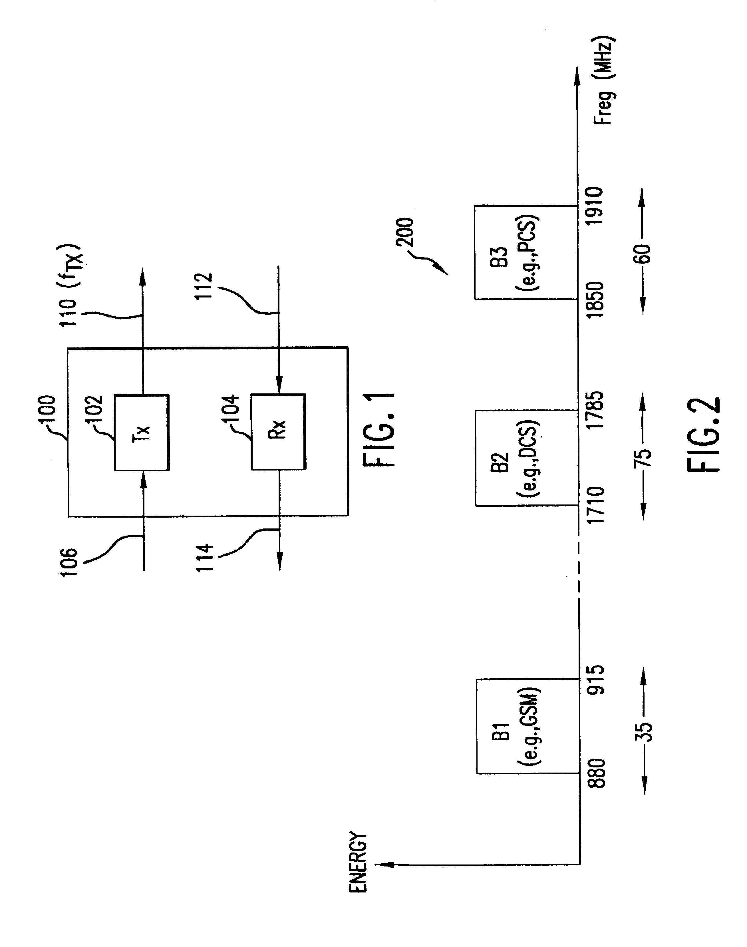
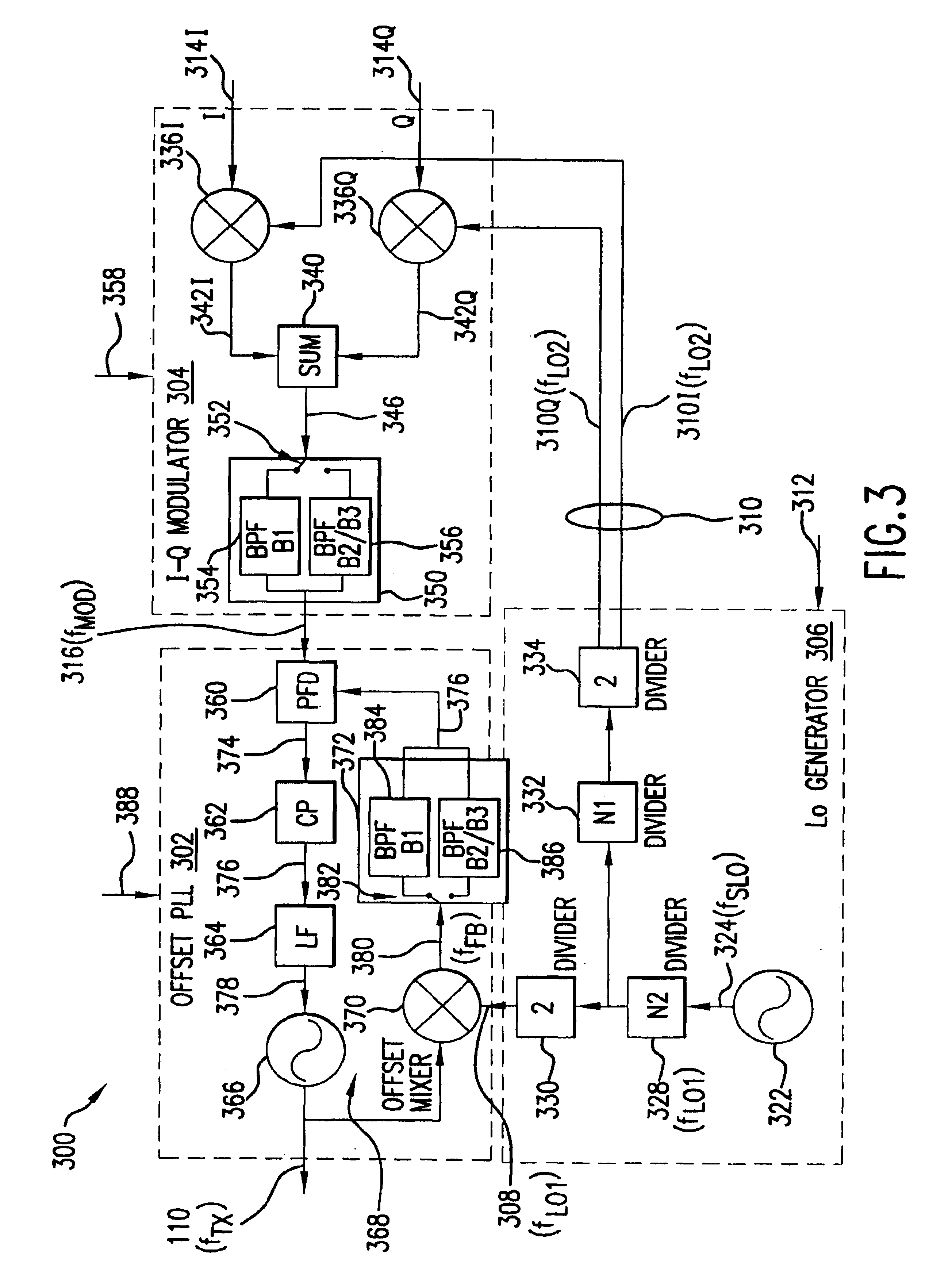
FIG. 1 is a block diagram of an example transceiver 100 in which the present invention may be used. Transceiver 100 includes a transmit (Tx) subsystem 102 of the present invention and a receive (Rx) subsystem 104. Transmitter 102 receives a baseband signal 106, including one or more signals-to-be-transmitted such as a voice signal, a computer data signal, a cable system based signal, and so on. Transmitter 102 modulates and frequency-upconverts baseband signal 106 to a modulated radio frequency (RF) signal 110. Transceiver 100 then transmits signal 110 to a remote location either wirelessly or over cables, for example. In accordance with the present invention, transmitter 102 generates transmit signal 110 at a frequency fTX corresponding to either one of at least two or more separated communication frequency bands. Transmitter 102 can tune / adjust the frequency fTX to coincide with the communication channels of each of the frequency bands.

Receiver 104 receives a modulated RF signal 1...


PUM


Abstract

A translational-loop transmitter includes a local oscillator (LO) generator for generating first and second LO signals, a modulator for generating a modulated reference signal using the second LO signal, and an offset phase-locked-loop (PLL) for phase-locking an output signal to the reference signal, and for tuning the output signal in accordance with the first LO signal. The PLL includes an offset mixer in a feedback path of the PLL, and operates in accordance with a frequency plan that minimizes the effects of on- and off-channel spurs at the output of the offset mixer.

Description

BACKGROUND OF THE INVENTION1. Field of the InventionThe present invention relates generally to transmitters, and particularly, to such a transmitter that operates in accordance with a frequency plan to reduce spurious energy in the transmitter.2. Related ArtA conventional communication transceiver includes a transmitter to generate an output signal having a tunable output signal frequency. One type of known transmitter is a translational-loop transmitter. The translational-loop transmitter includes an offset phase-locked-loop (PLL) to generate the output signal and phase-lock the output signal to a reference signal. The offset PLL includes an offset mixer in a feedback path of the PLL.Devices used in the offset PLL, particularly the offset mixer, may have non-linear device characteristics tending to give rise to undesired spurious energy, known as “spurs,” in the PLL. Often, the spurs are generated at frequencies and power levels that interfere with, and thus degrade, transmitter pe...

Claims


Application Information

Patent Timeline
IPC IPC(8): H04B1/04
CPCH04B1/0475H04B2001/0491
Inventor SHI, HONGCARR, FRANK
Owner AVAGO TECH WIRELESS IP SINGAPORE PTE
Why Eureka
Try Eureka