Liquid reservoir for nebulizer

Inactive Publication Date: 2005-03-22
INSTRUMENTARIUM CORP
View PDF34 Cites 1 Cited by
  • Summary
  • Abstract
  • Description
  • Claims
  • Application Information

AI Technical Summary

Benefits of technology

Briefly, the present invention contemplates such a liquid reservoir comprised of a pair of membranes formed of a resilient material. The membranes are positioned in an opposing relationship and sealed about their edges to form a closed chamber between them for containing the liquid to be nebulized. The chamber may be filled by a syringe or other appropriate means. Or, the chamber may be filled directly from a container through a check valve using a handle or other means, to draw the membranes apart in which case, the use of a syringe may be eliminated. When the chamber is filled with liquid and thereby expanded, the expansion of the chamber distends the resilient material membranes to apply pressure to liquid in the chamber. A flow control means, such as a valve, communicates with the chamber and controls the discharge of liquid from the reservoir to the nebulizer under the pressure applied to the liquid by the distended membranes.
The liquid reservoir is mounted on the nebulizer so that one of the membranes abuts a surface of the nebulizer which concavely deforms the membrane to increase the pressure applied to the liquid in the chamber. This pressure increase ensures that the liquid can be discharged from the chamber against any pressures generated in a breathing circuit to which the nebulizer is connected. It further renders the nebulizer insensitive to position as gases from the breathing circuit cannot enter and become trapped in the reservoir. Still further, it reduces or eliminates any residual volume of liquid in the chamber at the end of treatment, thereby ensuring that a patient receives the proper total dosage of a drug and avoiding wastage.
Inasmuch as the local liquid reservoir of the present invention does not use a pressurizing gas, the overall size of the reservoir can be advantageously reduced due to the absence of a gas chamber.

Problems solved by technology

It further renders the nebulizer insensitive to position as gases from the breathing circuit cannot enter and become trapped in the reservoir.

Method used


Image

  • Liquid reservoir for nebulizer
  • Liquid reservoir for nebulizer
  • Liquid reservoir for nebulizer

Examples


Embodiment Construction

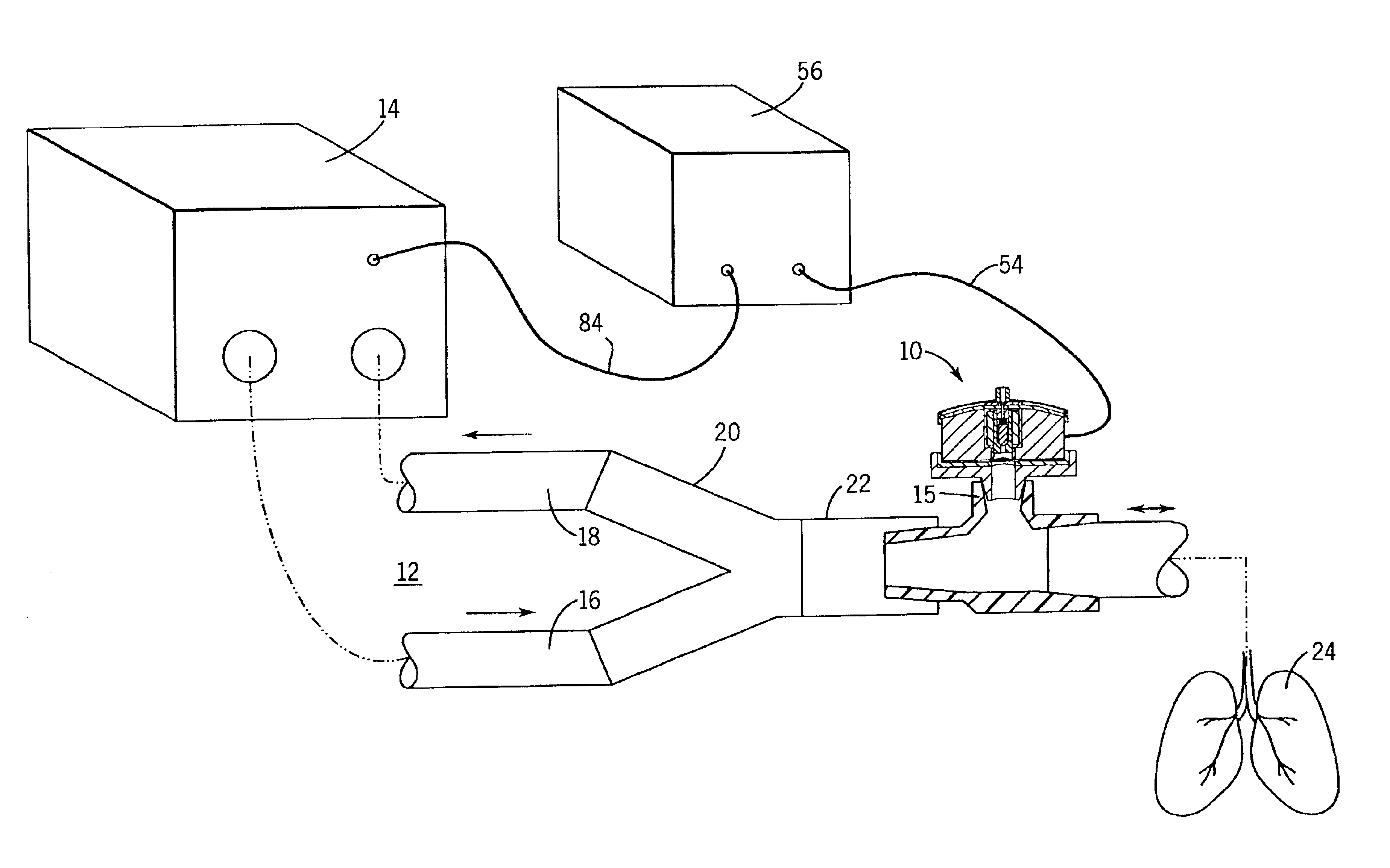
Nebulizer apparatus 10 of the present invention is typically used in conjunction with breathing circuit 12 and ventilator 14, as shown in FIG. 1. Nebulizer 10 atomizes liquid solutions or suspensions for delivery to a subject, as for example as a drug treatment for a patient. Breathing circuit 12 includes inhalation limb 16 coupled to ventilator 14. Exhalation limb 18 is also connected to ventilator 14. Inhalation limb 16 and exhalation limb 18 are connected to two arms of Y-connector 20. The third arm of Y-connector 20 is connected to one end of patient limb 22. The other end of patient limb 22 is connected to a mouthpiece, face mask, or endotracheal tube (not shown) for the subject for supplying respiratory gases to lungs 24 of a subject.

Ventilator 14 provides all or a portion of the respiratory gases for the subject by providing inhalation gases in inhalation limb 16. The inhalation gases pass through Y-connector 20 and into patient limb 22 for supply to the lungs 24 of the subje...


PUM


Abstract

A liquid reservoir for a nebulizer is comprised of a pair of membranes formed of resilient material and sealed about their edges to form a closed chamber between them for containing a liquid to be nebulized. When the chamber is filled with liquid and thereby expanded, the resilient membranes are distended to apply pressure to the liquid in the chamber. A discharge valve controls the discharge of liquid from the reservoir to the nebulizer under the pressure applied by the membranes. The reservoir is mounted on the nebulizer so that one of the membranes abuts a surface of the nebulizer that concavely deforms the membrane to increase the pressure applied to the liquid in the chamber to reduce or eliminate any residual volume of liquid in the chamber at the end of the discharging operation.

Description

BACKGROUND OF THE INVENTIONThe present invention relates to nebulizers and more particularly to an improved reservoir arrangement for containing a liquid to be nebulized.Nebulizers, or atomizers, are devices that generate a fine spray or aerosol. A particularly useful application for nebulizers is to convert aqueous drug solutions, or suspensions with non-dissolved particles, into an aerosol of small droplets that can thereafter be inhaled to administer the drug to a subject during breathing. Such inhalation treatment is highly effective for conditions effecting the subject's respiratory organs. Further, since the lungs are close to the heart and the blood circulatory system of the body, drug administration by inhalation provides an effective and rapid delivery system to all organs of the body.In many cases, the subject breathes with the aid of a respiratory ventilator. A typical ventilator has a breathing circuit comprising an inhalation limb and an exhalation limb connected to two...

Claims


Application Information

Patent Timeline
IPC IPC(8): A61M15/00A61M16/00A61M11/00
CPCA61M15/0085A61M11/001A61M2016/0024A61M11/005
Inventor HEINONEN, ERKKI
Owner INSTRUMENTARIUM CORP
Why Eureka
Try Eureka