
Display systems using organic laser light sources

Active Publication Date: 2005-03-22
EASTMAN KODAK CO
View PDF17 Cites 94 Cited by
  • Summary
  • Abstract
  • Description
  • Claims
  • Application Information

AI Technical Summary

Benefits of technology

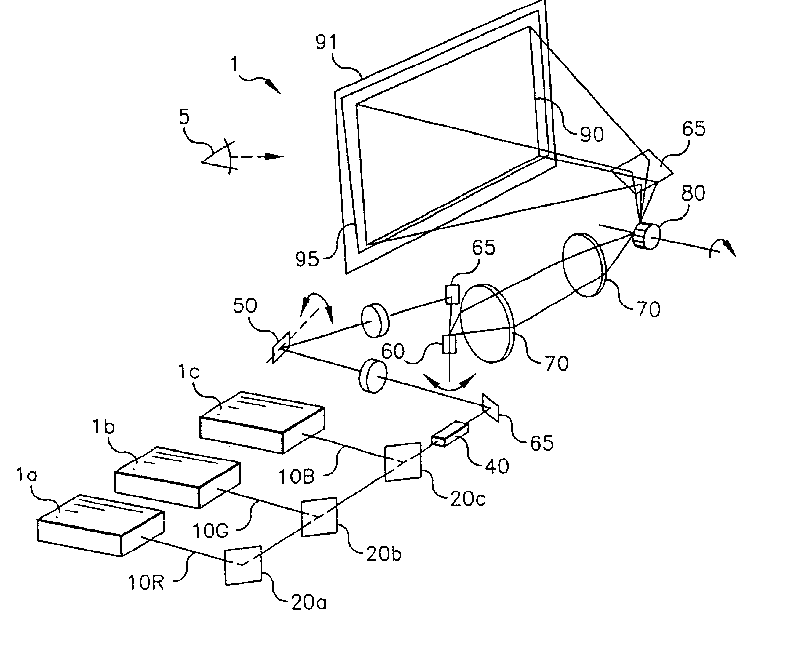
This object is achieved by a display system for providing a user viewable visible image, that includes: a) a view screen for receiving organic laser light and having a diffusing optical element 95 so that the view screen, in response to organic laser light, produces a viewable visible image, wherein the diffusing optical element 95 includes a viewing angle greater than 120° in a first viewing direction greater than and 60° in a second viewing direction orthogonal to the first viewing direction; b) one or more organic laser light sources arranged in an array with each of the laser light sources including a vertical cavity design having: i) a first dielectric stack for receiving and transmitting pump beam light and being reflective to laser light over a predetermined range of wavelengths; ii) an organic active region for receiving transmitted pump beam light from the first dielectric stack and emitting the laser light; and iii) a second dielectric stack for reflecting transmitted pump beam light and laser light from the organic active region back into the organic active region, wherein a combination of the first and the second dielectric stacks and the organic active region produces the laser light; c) means for projecting and modulating intensity of the organic laser light from the array onto the view screen in a pattern to cause a visual image to be produced by the viewscreen; and d) means associated with the viewscreen for reducing speckle in the organic laser light.
A feature of the present invention is the use of visible laser devices based upon vertical cavity organic laser light sources incorporating high reflectance dielectric multilayer mirrors for both the top and bottom dielectric stacks and having the active material composed of small molecular weight organic material. A consequence of the very low threshold for this vertical laser cavity design is that it is unnecessary to use high power density pump beam devices (i.e., focused laser light) in order to cause the organic cavity to laser. As a result, low power density devices, such as that produced by unfocused light emitting diode (LED) radiation, are sufficient light sources for pumping the laser cavities. Combining an organic-based laser cavity with an LED pump source results in an inexpensive and versatile laser light source whose light output can be tuned over a large wavelength range. This enables the fabrication of displays with low cost, high color gamut, reduced complexity, and high reliability to be produced from a design where the laser light source is scalable and may be patterned.

Problems solved by technology

A consequence of the very low threshold for this vertical laser cavity design is that it is unnecessary to use high power density pump beam devices (i.e., focused laser light) in order to cause the organic cavity to laser.

Method used


Image

  • Display systems using organic laser light sources
  • Display systems using organic laser light sources
  • Display systems using organic laser light sources

Examples


Embodiment Construction

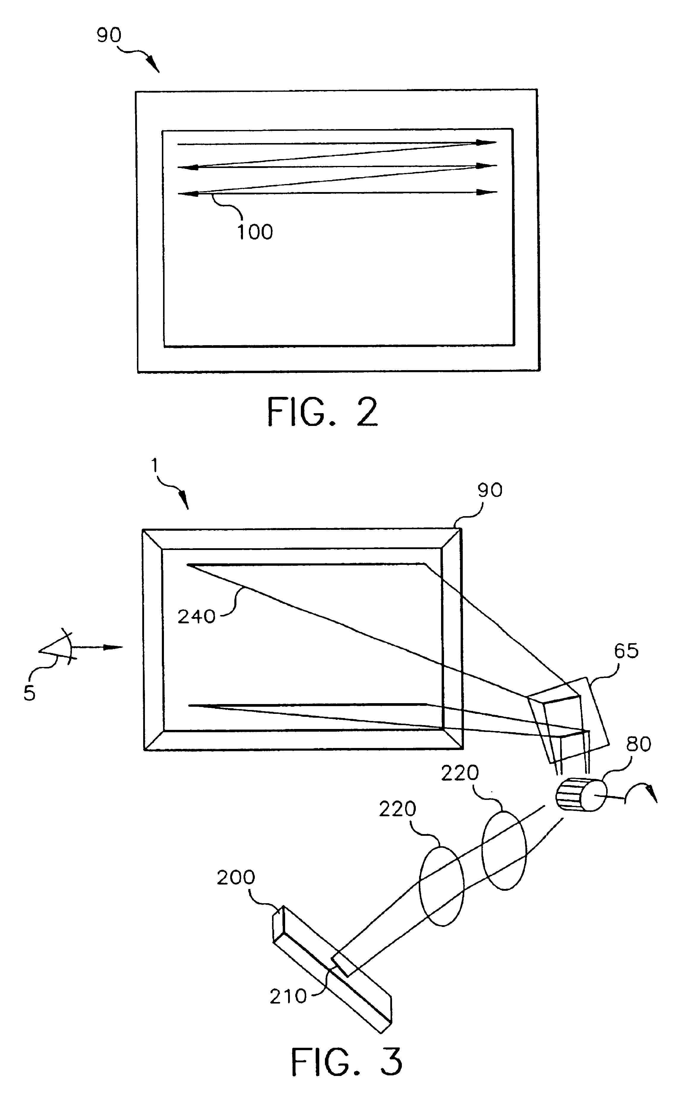
A display system 1 for providing a user viewable visible image is described that uses LED-pumped organic laser microcavity technology. Microcavity lasers with organic active media (gain media) may be used singly or patterned with necessary drive electronics onto a linear array structure. The microcavity lasers are designed with different organic gain media in order to produce devices that emit light with different visible wavelengths. The linear array length and microcavity laser density are such as to produce a high resolution projection display when the laser light is imaged onto a view surface. A single linear array emitting device is imaged to produce either a row or a column of color pixels in the viewed area. The image of the linear array is scanned across the viewed area by means of a single scan device or multiple scan devices to produce a full image in the viewed area.

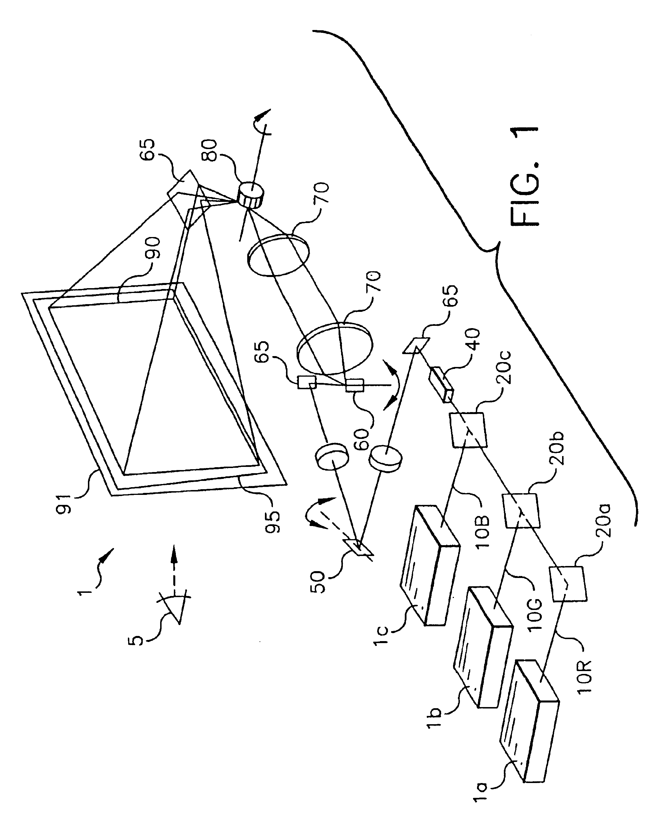
FIG. 1 illustrates a schematic view of a display system 1 in which three separate organic laser devices 1a,...


PUM


Abstract

A display system for providing a user viewable visible image, includes a view screen for receiving organic laser light and having a diffusing optical element so that the view screen, in response to organic laser light, produces a viewable visible image, wherein the diffusing optical element includes a viewing angle greater than 160° in a first viewing direction and greater than 100° in a second viewing direction orthogonal to the first direction; one or more organic laser light sources arranged in an array with each such laser light source including a vertical cavity design and means for projecting and modulating the intensity of the organic laser light from the array onto the view screen in a pattern to cause a visual image to be produced by the view screen; and means associated with the view screen for reducing speckle in the organic laser light.

Description

FIELD OF THE INVENTIONThe present invention relates to display systems and, more particularly, to display systems that use organic laser light sources.BACKGROUND OF THE INVENTIONWhile display devices based upon laser light sources have been known for some time, their performance limitations have presented a barrier to many desirable applications. This is especially true for color display applications where the complexity and cost of using readily available, multiple, independent laser devices precludes large acceptance of these devices. Additionally, although lasers are an ideal light source for such applications from an intensity or brightness perspective, the coherence of the laser light generates speckle that is unpleasant to the viewer.Display devices based on laser light sources depend upon the generation of multiple wavelengths of light in order to produce a color display. The color is created by appropriately mixing such light sources to achieve a high color quality; the meas...

Claims


Application Information

Patent Timeline
IPC IPC(8): H04N9/31G03B21/56G09G3/02H01S3/00H01S3/16
CPCH04N9/3132G03B21/56
Inventor KAMINSKY, CHERYL J.BOURDELAIS, ROBERT P.KAHEN, KEITH B.LEBENS, JOHN A.SPOONHOWER, JOHN P.
Owner EASTMAN KODAK CO
Learn More