Thermo-optic wave-guide switch

a technology of thermo-optic waveguide switch and waveguide, which is applied in the direction of optical waveguide light guide, instruments, optics, etc., can solve the problems of analog optical switch being susceptible to wavelength, huge variation of cross-talk, and periodic output intensity of heat power, so as to reduce the cross-talk value of thermo-optic waveguide switch and the effect of extensive temperature rang

Inactive Publication Date: 2005-06-28
IND TECH RES INST
View PDF7 Cites 0 Cited by
  • Summary
  • Abstract
  • Description
  • Claims
  • Application Information

AI Technical Summary

Benefits of technology

[0012]The invention has an advantage of extensive wavelength range for operating the thermo-optic wave-guide switch. The operating wavelength is ranged at least from 1530 nm to 1610 nm.
[0013]The invention has another advantage of extensive temperature range for operating the thermo-optic wave-guide switch. The operating temperature is ranged at least from −5° C. to 75° C.
[0014]The invention has a further advantage of decreasing the cross-talk value of the thermo-optic wave-guide switch to −40 dB.
[0015]The invention has the further advantage of providing a digital switch with relatively fast switch response. The switch response time is not greater than 6.5 ms.
[0016]The invention has the further advantage of decreasing the polarization-dependent-loss of the thermo-optic wave-guide switch, wherein the polarization-dependent-loss is not greater than 0.07 dB.
[0017]The invention has yet a further advantage of providing a thermo-optic wave-guide switch with small volume.

Problems solved by technology

However, one disadvantage of the analog optical switch is that the output intensity thereof corresponding to the heat power is periodic and thus sensitive.
In other words, the slight variation of the heat power of the heater causes huge variation of cross-talk.
Furthermore, another disadvantage of the analog optical switch is susceptible to wavelength, and then the wavelength range applied to the analog optical switch is rather limited.
Moreover, large volume analog optical switches have other disadvantage.
However, the disadvantage of the digital optical switch is that providing the branches of the Y-type wave-guide with huge index difference needs too much heat.

Method used


Image

  • Thermo-optic wave-guide switch
  • Thermo-optic wave-guide switch
  • Thermo-optic wave-guide switch

Examples


first embodiment

[0035]The optical switch of the invention utilizes a multimode interference (MMI) structure. The incident field is coupled into several waveguide modes when launched into the multimode region. For each waveguide mode, the coupling efficiency is proportional to the overlap integral field and incident filed. Each waveguide mode has different effective refractive index, i.e., each waveguide mode has different phase change while propagating the same path length. Under a certain length of propagation, every waveguide mode can have the same phase change and interference of all the modes, forming a mirror image of the incident field with respect to the center of the multimode waveguide. This phenomenon is called “self-image.” Thus, a cross-state switch in an optical waveguide can be simply implemented, and the incident field launched from an input port thereof can be received by an output port in opposite position with respect to the center of the multimode waveguide.

[0036]Because effectiv...

second embodiment

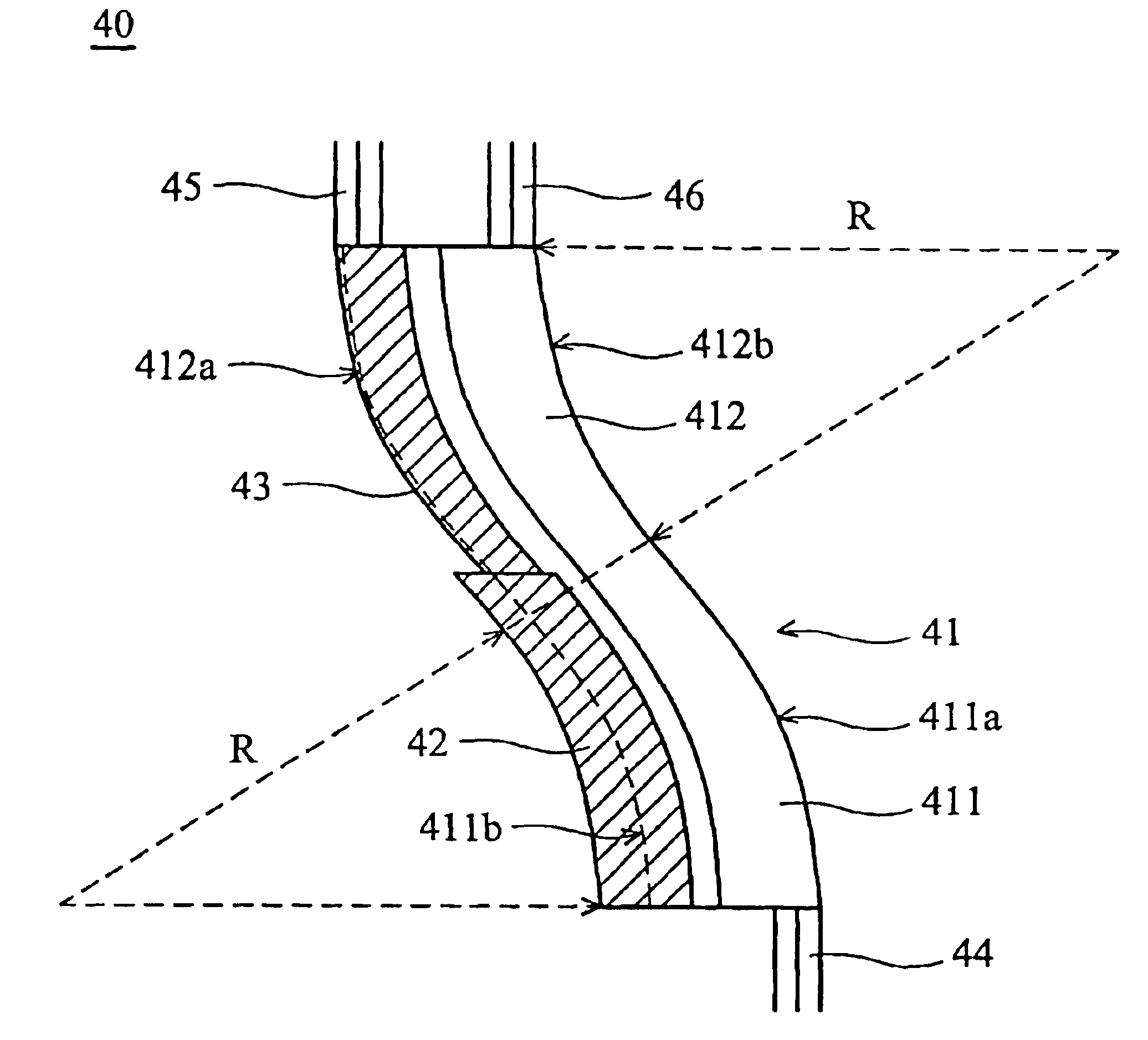
[0041]FIG. 5 schematically shows a thermo-optic wave-guide switch according to the second embodiment of the invention. As shown in FIG. 5, the thermo-optic wave-guide switch 40 of the second embodiment of the invention is a bent structure and has a multi-mode wave-guide 41, wherein the multi-mode wave-guide 41 further includes a first crooked portion 411 and a second crooked portion 412. In the second embodiment of the invention, the first crooked portion 411 has a first outer curve 411a and a first inner curve 411b with a predetermined curvature radius R, and the second crooked portion 412 has a second outer curve 412a and a second inner curve 412b with the same curvature radius R. The first crooked portion 411 connects the second crooked portion 412 whereby the first outer curve 411a connects the second inner curve 412b and the first inner curve 411b connects the second outer curve 412a. In the second embodiment of the invention, the multi-mode wave-guide 41 has a thermo-optic pro...


PUM

PropertyMeasurementUnit
operating wavelengthaaaaaaaaaa
operating temperatureaaaaaaaaaa
switch response timeaaaaaaaaaa

Abstract

A thermo-optic wave-guide switch. The switch selectively switches the paths of an optical signal. The thermo-optic wave-guide switch includes a multi-mode wave-guide having an input port, a first output port and a second output port, and a thin film heater formed on the side of the multi-mode wave-guide. When the thin film heater does not provide the multi-mode wave-guide with heat and a signal is received by the input port, the first output port outputs the signal in a cross state according to the self-image theorem, and when the thin film heater provides the multi-mode wave-guide with heat and a signal is received by the input port, the second output port outputs the signal in a bar state.

Description

BACKGROUND OF THE INVENTION[0001]1. Field of the Invention[0002]The invention relates to a thermo-optic wave-guide switch, and more particularly to a thermo-optic wave-guide switch triggered by heating a multi-mode wave-guide.[0003]2 . Description of the Related Art[0004]FIG. 1A schematically shows a conventional optical switch. As shown in FIG. 1A, the conventional optical switch 10 has a Mach-Zehnder Interferometer 2 formed by a pair of optical wave-guides 1a, 1b and covered with a heater 3. When the heater 3 heats one of the optical wave-guides 1a, 1b, the output of the optical switch 10 is periodical. FIG. 1B schematically shows the periodic output of the conventional optical switch corresponding to different levels of output from the heater. As shown in FIG. 1B, the conventional optical switch 10 is an analog optical switch.[0005]However, one disadvantage of the analog optical switch is that the output intensity thereof corresponding to the heat power is periodic and thus sensi...

Claims


Application Information

Patent Timeline
Patent Type & Authority Patents(United States)
IPC IPC(8): G02F1/29G02F1/313G02F1/01
CPCG02F1/3137G02F1/0147G02F2201/05
Inventor SHU, KING-CHANGHUANG, DING-WEICHIU, TSUNG-HSUANLAI, YINCHIEH
Owner IND TECH RES INST
Why Eureka
Try Eureka