Tissue biopsy and treatment apparatus and method

a tissue biopsy and treatment apparatus technology, applied in the field of methods, can solve the problems of necrosis of the selected target tissue, current ablative technology has failed to recognize and therefore, properly address these requirements, and achieve the effect of improving the clinical outcome of the procedur

Inactive Publication Date: 2005-03-22
ANGIODYNAMICS INC
View PDF29 Cites 1224 Cited by
  • Summary
  • Abstract
  • Description
  • Claims
  • Application Information

AI Technical Summary

Benefits of technology

Yet another embodiment of the invention includes a method for tumor detection, wherein a primary optically labeled marker or antibody is infused into a patient or injected into a target tissue or organ site containing a tumor and specifically binds to a marker produced by or associated with a tumor. The target tissue or organ site is scanned with a biopsy ablation apparatus including a sensor array and the binding sites of the labeled marker antibody are located by detecting elevated levels of optical label signal intensity at such sites with the sensor array. This information can be digitally stored and displayed on a monitor device to accurately position the biopsy ablation apparatus within the tumors to deliver energy to necrose or ablate

Problems solved by technology

These methods cause physiological and structural changes intended to cause necrosis of the selected target tissue.
During ablative procedures of diseased and other abnormal tissue, clinicians encounter numerous difficulties and challenges, these include (i) locating the target tissue, (ii) the need to perform a b

Method used


Image

  • Tissue biopsy and treatment apparatus and method
  • Tissue biopsy and treatment apparatus and method
  • Tissue biopsy and treatment apparatus and method

Examples


Embodiment Construction

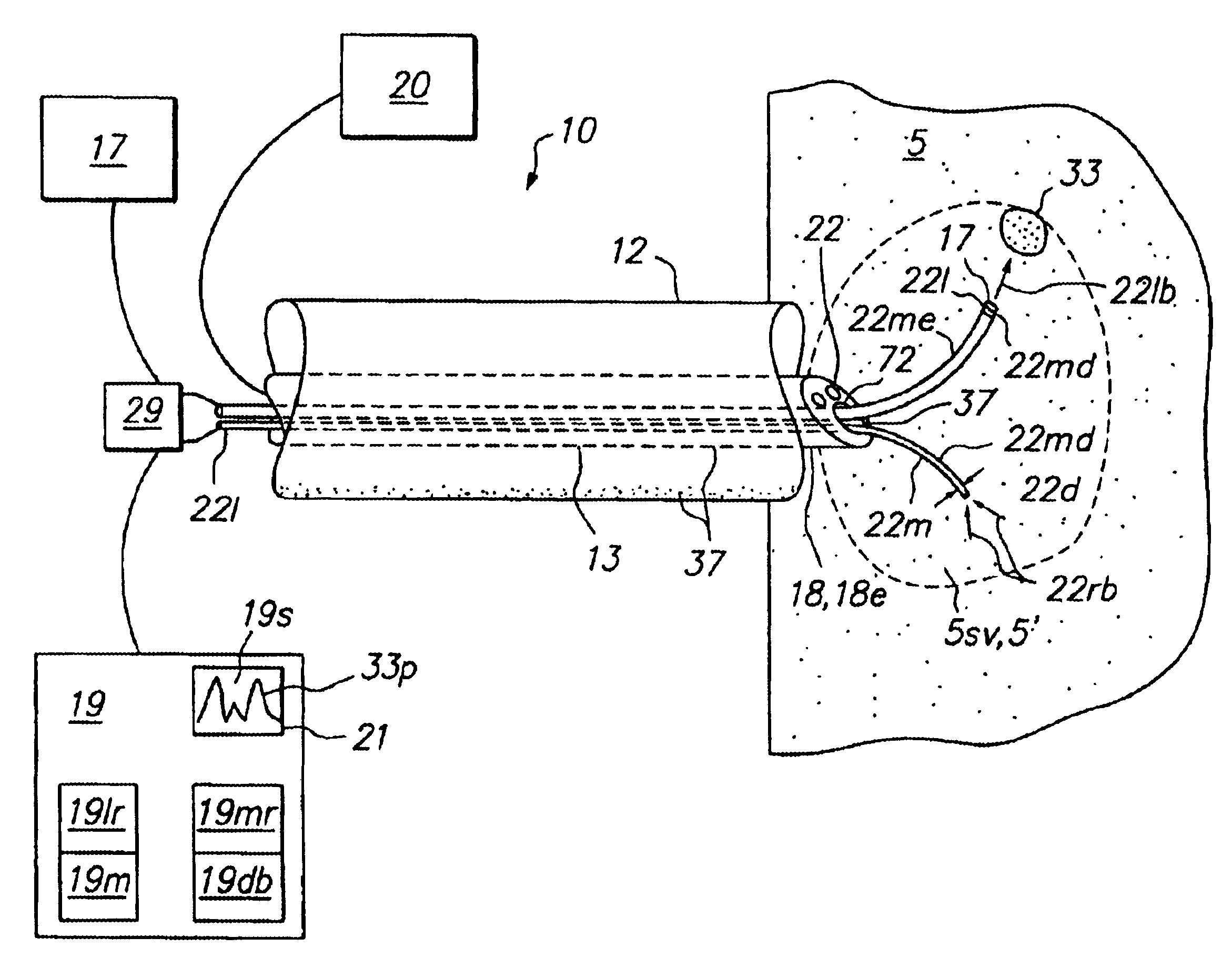
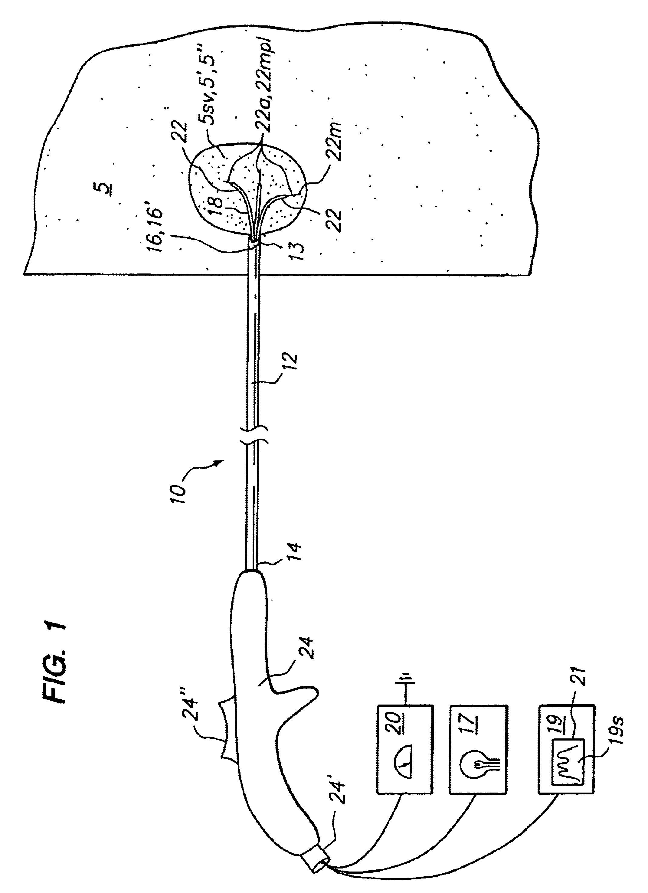
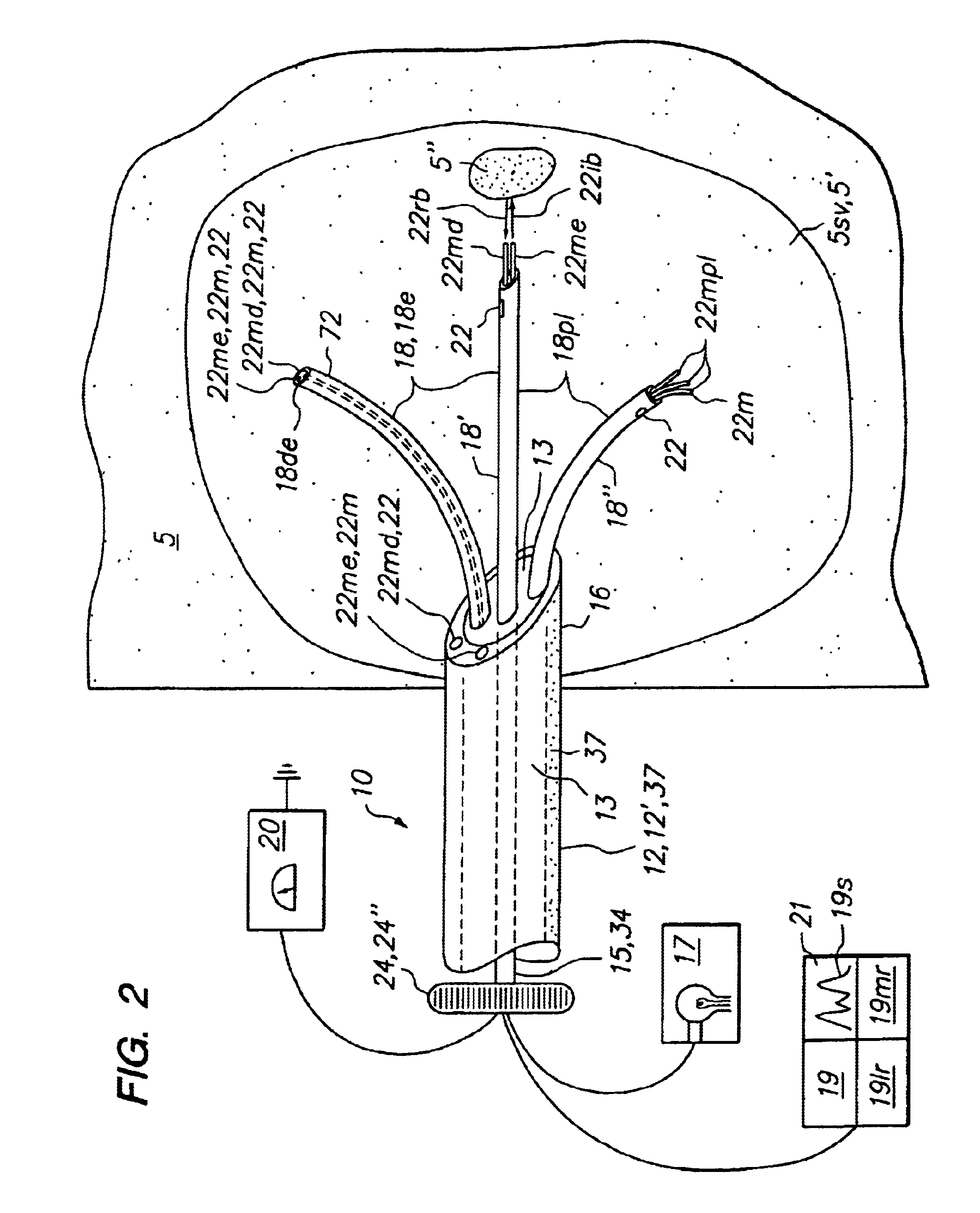
Embodiments of the present invention provide a method and apparatus to optically biopsy a tissue and use the information to diagnose a tumor, accurately position an energy delivery device, visually monitor and confirm complete ablation of the tumor. Further embodiments of the invention include one or more sensing members or sensing arrays that can be deployed independently or simultaneously to enable probing of target tissue by optical or other means. Deployment of each array is controlled such that telemetry can be used with optical, temperature and impedance feedback to both identify tissue and map the topography of tissue types and structures to facilitate proper placement of an energy delivery device to ablate the tumor. These and other embodiments of the invention allow for the control and determination of a clinical endpoint while significantly reducing the risk of incomplete ablation or unwanted damage to critical anatomical structures due to improper device placement.

Specifi...


PUM

PropertyMeasurementUnit
Temperatureaaaaaaaaaa

Abstract

An embodiment of the invention provides a tissue biopsy and treatment apparatus that comprises an elongated delivery device that is positionable in tissue and includes a lumen. A sensor array having a plurality of resilient members is deployable from the elongated delivery device. At least one of the plurality of resilient members is positionable in the elongated delivery device in a compacted state and deployable with curvature into tissue from the elongated delivery device in a deployed state. At least one of the plurality of resilient members includes at least one of a sensor, a tissue piercing distal end or a lumen. The sensor array has a geometric configuration adapted to volumetrically sample tissue at a tissue site to differentiate or identify tissue at the target tissue site. At least one energy delivery device is coupled to one of the sensor array, at least one of the plurality of resilient members or the elongated delivery device.

Description

FIELD OF THE INVENTIONThis invention relates generally to a method for performing an in vivo tissue biopsy sample using minimally invasive methods. More particularly, the invention to relates to method and apparatus for performing in vivo tissue biopsy using optical methods. Still more particularly, the invention relates to a method and apparatus for performing an in vivo tissue biopsy to discriminate between diseased and healthy tissue and facilitate tissue treatment.BACKGROUND OF THE INVENTIONVarious ablative procedures can be used to treat diseased and / or abnormal tissue. These methods cause physiological and structural changes intended to cause necrosis of the selected target tissue. During ablative procedures of diseased and other abnormal tissue, clinicians encounter numerous difficulties and challenges, these include (i) locating the target tissue, (ii) the need to perform a biopsy and diagnose diseased tissue versus healthy tissue, (iii) correct device placement, (iv) monito...

Claims


Application Information

Patent Timeline
IPC IPC(8): A61B18/12A61B18/14G02F1/13G02F1/1343A61B17/22A61B18/00A61B19/00A61B10/00A61B17/00G02F1/1362G02F1/1333A61B1/00A61B10/02A61B17/34
CPCA61B18/1206A61B18/1477A61B10/02C08L2201/12A61B18/00A61B18/1482A61B18/1815A61B19/54A61B2017/00022A61B2017/00061A61B2017/003A61B2017/00849A61B2017/00867A61B2017/22082A61B2018/00029A61B2018/00083A61B2018/00142A61B2018/00577A61B2018/00642A61B2018/00654A61B2018/0069A61B2018/00702A61B2018/00791A61B2018/00797A61B2018/00821A61B2018/00827A61B2018/00875A61B2018/00892A61B2018/124A61B2018/143A61B2018/1432A61B2018/1472A61B2018/1861A61B2019/464A61B2019/5278A61B2019/5441A61B2019/5466A61B2218/002A61N7/02A61B10/0283A61B2090/3782A61B2090/064A61B90/39A61B2090/3941A61B2090/3966A61B5/0071
Inventor BALBIERZ, DANIEL J.JOHNSON, THEODORE
Owner ANGIODYNAMICS INC
Why Eureka
Try Eureka