Method for tibial nail insertion

a technology of tibial nail and insertion device, which is applied in the field of tibial nail insertion device, can solve problems such as iatrogenic fractures, and achieve the effects of improving clinical outcome, improving insertion characteristics, and avoiding hammering

Active Publication Date: 2014-12-30
STRYKER EURO OPERATIONS HLDG LLC
View PDF4 Cites 50 Cited by
  • Summary
  • Abstract
  • Description
  • Claims
  • Application Information

AI Technical Summary

Benefits of technology

[0007]A smoother nail design with obtuse bends or even curvatures instead of acute-angled bends may provide improved insertion characteristics, avoid hammering and thus improve the clinical outcome.
[0013]1) The approach permits not only a design for a dedicated left and a dedicated right nail, but also a universal design for combined left and right nails with an either constant retro-curved radius or a smooth connection between the established Herzog bend of the nail, its shaft and possible distal bend. The smooth design in turn may improve the insertion characteristics significantly, avoid intensive hammering and iatrogenic fractures which remains to be verified.
[0014]2) Owing to the triangular shaped tibia shaft, drilling for all proximal and distal mediolateral screws will be carried out more perpendicular to the medial cortex preventing sliding of the drill.
[0015]3) Additionally, the drilling and locking procedure will be simplified for the surgeon due to the laterally orientated target arm and thus the external dislocation of the operating field with better accessibility.
[0016]4) In case of a universal nail design for a combined left and right nail, all screws in the tibial plateau have to be placed symmetric to the longitudinal nail axis at an angle of between 40 and 50 degrees, preferably a 45 degrees angle between both proximal screws and symmetric plane, in order to guarantee that their tips penetrate the cortex in equivalent spots but at slightly different heights if the whole construct is rotated left and right. These new screw trajectories in the tibial plateau also reduce the risk of penetrating the tibiofibular joint.
[0017]5) Furthermore, this principle is considered to be used for control, restoration and adjustment of the correct rotation. Obviously, there seems to be a dependency between the natural rotation of the ankle and the natural symmetry plane of the tibia defined by the tuberositas tibiae. The idea is to use this correlation to control the rotation. This landmark-based approach, i.e. orienting the tuberositas tibia to the natural external rotation of the ankle during fracture reduction, is not geared to the healthy contra lateral side and will potentially be more accurate, reduce operation room time and thus improve the clinical outcome. The technique of the present invention is thus not geared to the healthy contra lateral side and will potentially be more accurate, reduce operation room time and thus improve the clinical outcome.

Problems solved by technology

Tibial nailing often requires intensive hammering during insertion which might cause iatrogenic fractures.
Getting the rotation correct after intramedullary nailing is a clinical challenge, especially for the femur.

Method used


Image

  • Method for tibial nail insertion
  • Method for tibial nail insertion
  • Method for tibial nail insertion

Examples


first embodiment

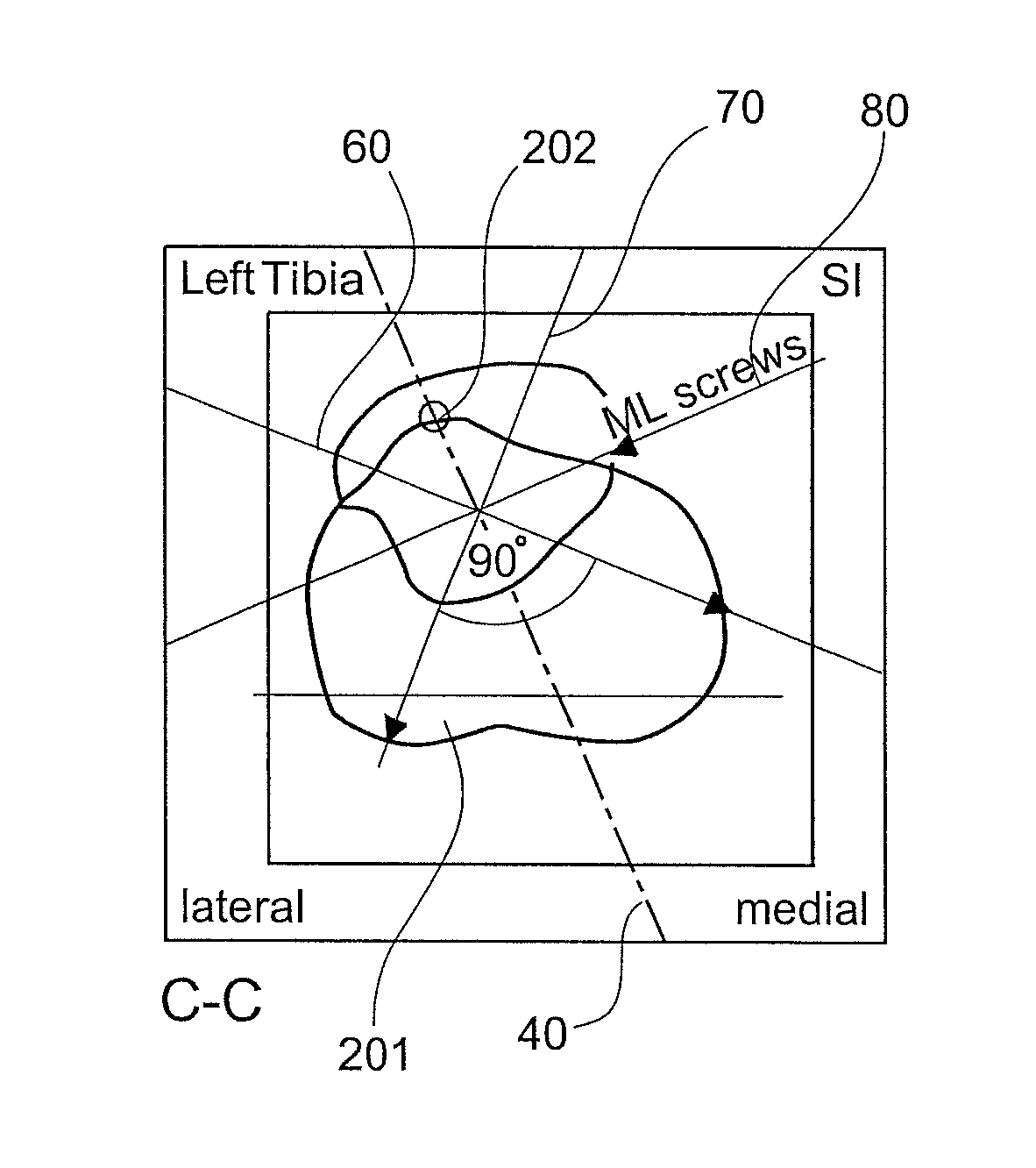
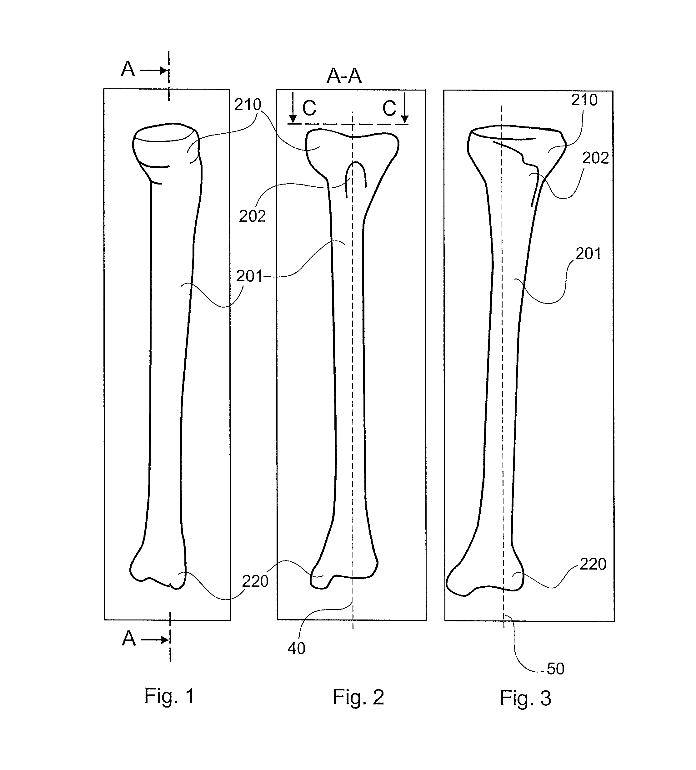
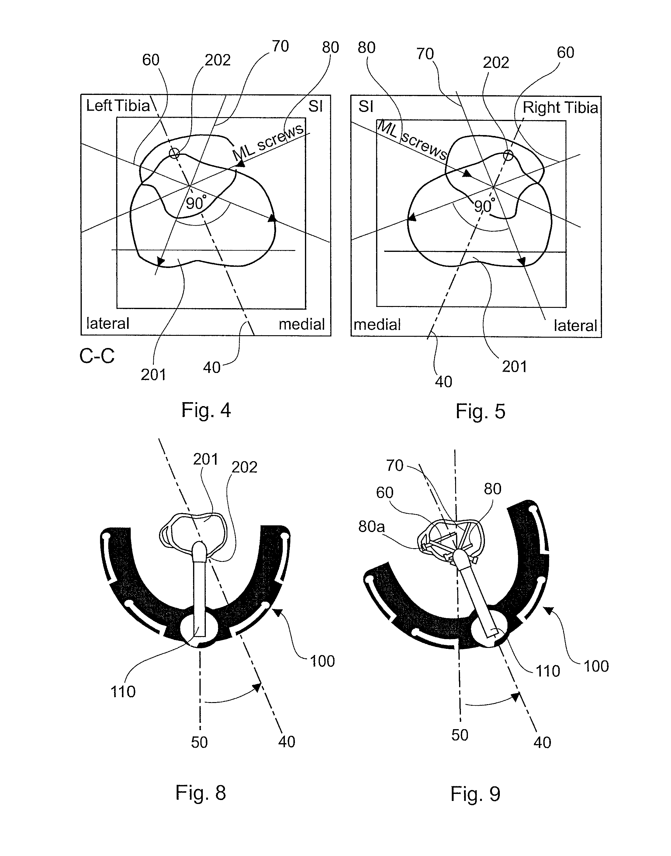
[0051]In a next step, in accordance with the invention, the tuberositas tibiae plane is identified. This identification is performed by firstly identifying the tuberositas tibiae and the entry point into the medullary channel on the upper surface of the tibia, and secondly by identifying the axis of the medullary channel. The tuberositas tibiae, the entry point as well as the axis of the medullary channel lie on the tuberositas tibiae plane.

[0052]The intramedullary nail is aligned in a following step, such that the radius of the curved section of the intramedullary nail lies in the tuberositas tibiae plane.

second embodiment

[0053]Alternatively, in accordance with the invention, a sagittal plane of the tibia is identified.

[0054]Then, the intramedullary nail is firstly aligned with the sagittal plane, i.e. the radius of the intramedullary nail lies in the sagittal plane, and secondly is externally rotated by an angle between 13 degrees to 37 degrees with respect to the sagittal plane orientation of the tibia previously determined.

[0055]In a subsequent step, the intramedullary nail is inserted into a marrow channel of the tibia through an entry point in the tibial plateau.

[0056]Finally, screws may further be placed in a tibia plateau of the tibia into which the intramedullary nail is to be inserted. The actual position and orientation of each screw depends on the actual design of the driving end portion of the intramedullary nail. Finally, further locking screws are inserted through transverse bores in the non-driving end portion of the nail, so that the distal portion of the tibia may be reliably fixed r...


PUM


Abstract

A method for implanting a longitudinal intramedullary nail into the tibia comprises inserting the tibia nail along a plane of symmetry through the tuberositas tibiae. Thereby, the tuberositas tibiae can be used during nail insertion to correctly align the nail and the target arm to the symmetry plane of the bone. This means, that the whole construct, the nail attached to the target arm, has to be inserted in external rotation.

Description

BACKGROUND OF THE INVENTION[0001]The invention generally relates to methods for tibial nail insertion. In particular, the invention relates to a method for implanting a longitudinal intramedullary nail into a tibia.[0002]Tibial nailing often requires intensive hammering during insertion which might cause iatrogenic fractures.[0003]Getting the rotation correct after intramedullary nailing is a clinical challenge, especially for the femur. However, tibial malrotation after intramedullary nailing is likely more common than reported. The cases of three patients who incurred symptomatic rotational deformities after closed intramedullary nailing are reported in Kevin M. Kahn, M D, et al. “Malrotation after locked intramedullary tibial nailing: Three case reports and review of the literature” (The Journal of TRAUMA, Vol. 53, Number 3, pages 549 to 552). Today, the rotation of a fractured tibia is compared to its non-fractured counterpart, respectively. The rotation is generally evaluated m...

Claims


Application Information

Patent Timeline
Patent Type & Authority Patents(United States)
IPC IPC(8): A61B17/72A61B17/56
CPCA61B17/72A61B17/56A61B2017/564A61B17/725
Inventor HOMEIER, ANNIKAHOWLING, ILANZANDER, NILSKUHNE, LOTHARGRACA, CLAUDIA
Owner STRYKER EURO OPERATIONS HLDG LLC
Why Eureka
Try Eureka