Alignment system for bone fixation

a bone fixation and alignment system technology, applied in the field of alignment systems for bone fixation, can solve the problems of increasing the length of time a patient has to undergo an operation, unable to provide devices or guides, and unable to aid in the correctness, so as to reduce radiation, shorten the operation time, and reduce the risk of possible complications

Inactive Publication Date: 2005-03-22
CHOI SOON C
View PDF9 Cites 45 Cited by
  • Summary
  • Abstract
  • Description
  • Claims
  • Application Information

AI Technical Summary

Benefits of technology

One embodiment of the invention is directed to a new alignment guide to aid a surgeon in centering the guide pin to be inserted in the femoral head and neck without repeated trial-and-error drilling. This shortens the operation time and reduces the radiation due to prolonged exposure to fluoroscopic equipment and reduces the risk of possible complications from the surgery.

Problems solved by technology

However, no device or guide is available at this time to aid in the correct placement of lag screws or blades in the center of the femoral head and neck.
This trial-and-error adjustment increases the length of time a patient has to undergo an operation.
It also increases the risk of bleeding, wound contamination and subsequent infection.
It also increases the likelihood of bone damage from repeated drilling and potential iatrogenic fractures.
This also adds unnecessary radiation exposure to the patient, surgeon, and other operating room personnel.
It should also be noted that inadvertent drilling beyond the articular surface of the femoral head is a problem with the presently available systems.
Also, it is frequently difficult to confirm the position of the guide pin in central axis or near the central axis line of the femoral neck and head because the drill guide and its handle hide the true lateral view of the femoral head and neck even where a radio-lucent drill guide is used.

Method used


Image

  • Alignment system for bone fixation
  • Alignment system for bone fixation
  • Alignment system for bone fixation

Examples


Embodiment Construction

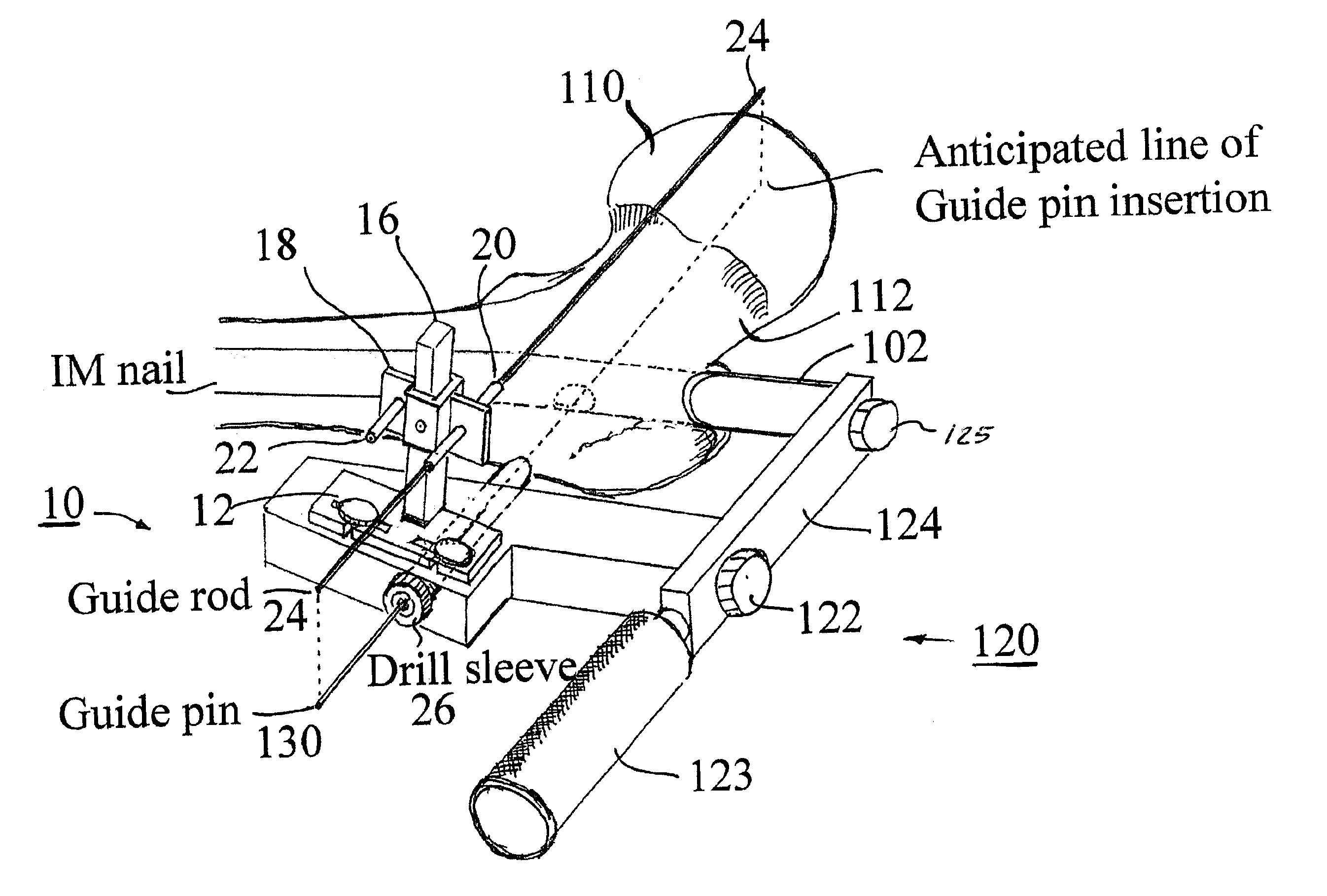
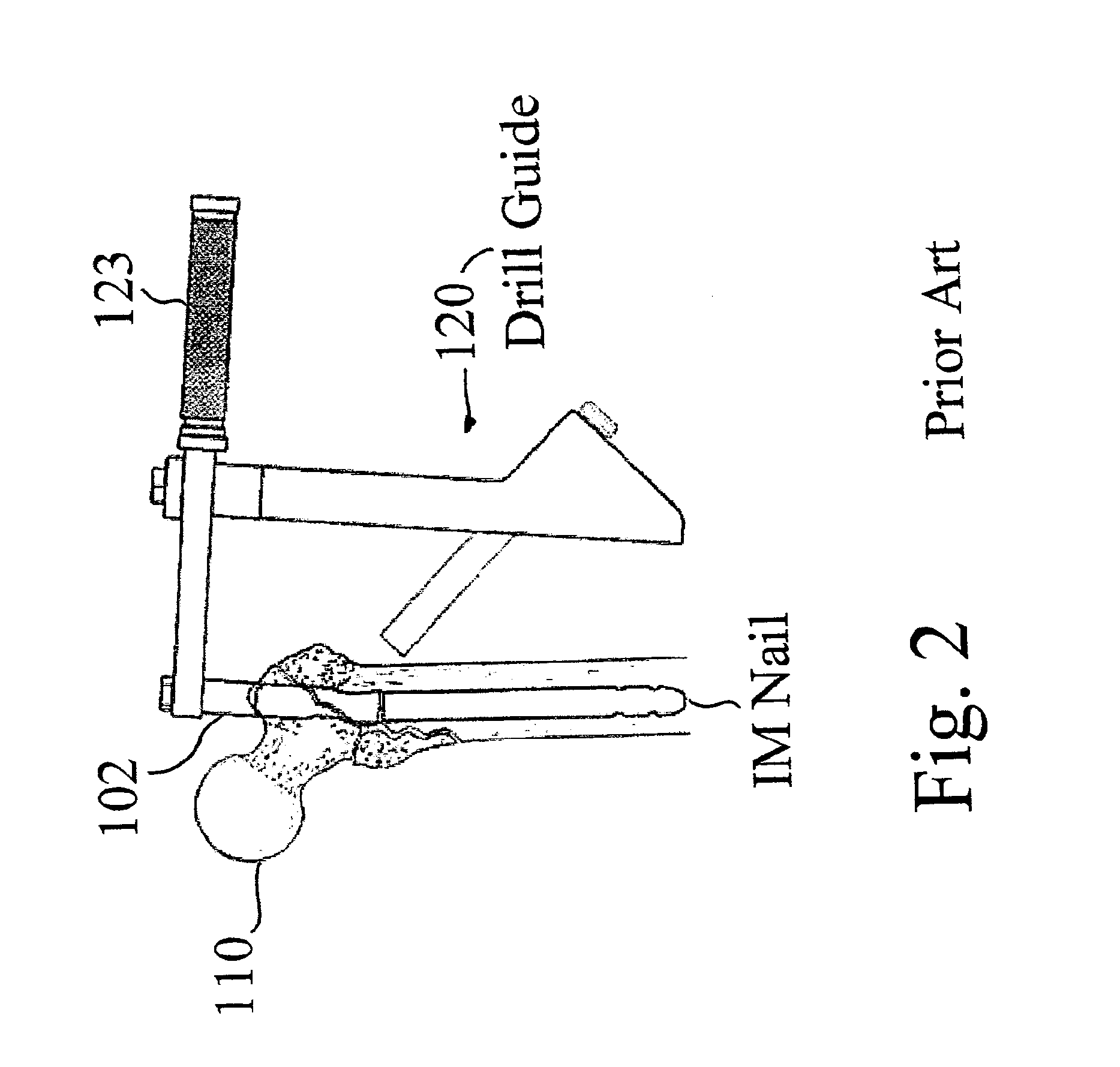
FIGS. 5-7 show various aspects of the apparatus embodying the invention. Different views of the alignment guide 10 embodying the invention are shown in FIGS. 5A, 5B, 5C and 5D. The alignment guide 10 is designed to be mounted on a drill guide 120 (see FIGS. 6A, 6B) to help determine the positioning and orientation of the drill guide 120 to ensure that a guide pin 130 is inserted into a selected bone at the appropriate angle (laterally and vertically) and for the desired distance (depth). The alignment guide 10 includes a mechanical assembly for deploying a calibrated guide rod 24 along the surface of a selected bone. The tip of the guide rod 24 may be pointed to enable it to penetrate soft tissue surrounding the selected bone; but the tip of the guide rod is blunt enough to avoid injury to neurovascular structures. The alignment guide 10 is linked to the drill guide 120 so that when the drill guide is used to insert a guide pin into the selected bone, the guide pin is inserted into ...


PUM


Abstract

An alignment guide for setting the position and depth of a guide pin to be inserted into a bone. The alignment guide includes a mechanical assembly for deploying a calibrated guide rod along a selected external surface of the bone and for adjusting the guide rod so it lies parallel to a desired path extending through the bone for a selected distance. The position and orientation of the guide rod may be adjusted using imaging means for viewing the location of the desired path extending through the bone parallel to the guide rod. The alignment guide is mechanically linked to apparatus for subsequently inserting a guide pin into the bone parallel to the guide rod. In one embodiment the alignment guide is designed to aid a surgeon in centering the guide pin to be inserted in the femoral head and neck without repeated trial-and-error drilling. This shortens the operation time and reduces the radiation due to prolonged exposure to fluoroscopic equipment and reduces the risk of possible complications from the surgery.

Description

BACKGROUND OF INVENTIONThis invention relates to apparatus and methods for more precisely aligning guide rods and guide pins into bones for bone fixation.To better understand the problem faced by the inventor and resolved by the invention reference will first be made to the prior art shown in FIGS. 1-4.Currently available femoral nail systems for the fixation of femoral or certain types of hip fracture and the prophylactic fixation of pending hip or femoral fracture have been described in several trade publications including: (a) The Titanium Femoral Nail System (Synthes); (b) TRIGEN® IM Nail System (Smith+Nephew, Inc.); (c) Intramedullary Hip Screw Nail (Smith+Nephew, Inc.); (d) M / DN® Intramedullary Fixation (Zimmer, Bristol Myers Squibb Co.); (e) AIM® Titanium Femoral Nail System (DePuy ACE, Johnson & Johnson Co); (f) GAMMA Locking Nail (Howmedica); and (g) UNIFLEX Nailing System (BIOMET). These known systems have design features, as shown in FIGS. 1A, 1B, and 1C, which allow inse...

Claims


Application Information

Patent Timeline
Patent Type & Authority Patents(United States)
IPC IPC(8): A61B17/17A61B17/16A61B17/90
CPCA61B17/1721A61B17/1703
Inventor CHOI, SOON C.
Owner CHOI SOON C
Why Eureka
Try Eureka