Methods and apparatus for EMI shielding

Inactive Publication Date: 2005-03-22
LAIRD TECH INC
View PDF16 Cites 83 Cited by
  • Summary
  • Abstract
  • Description
  • Claims
  • Application Information

AI Technical Summary

Benefits of technology

One purpose of this invention is to provide improved durability to EMI shielding honeycomb filters. An

Problems solved by technology

During normal operation, electronic equipment generates undesirable electromagnetic energy that can interfere with the operation of proximately located electronic equipment due to EMI transmission by radiation and conduction.
Since such enclosures often include vent openings and gaps or seams between adjacent access panels and around doors, effective shielding is difficult to attain, because the gaps in the enclosure permit transference of EMI therethrough.
Further, in the case of electrically conductive metal enclosures, these gaps can inhibit the beneficial Faraday Cage Effect by forming discontinuities in the conductivity of the enclosure which compromise the efficiency of the ground conduction path through the enclosure.
Moreover, by presenting an electrical conductivity level at the gaps that is significantly different from that of the enclosure generally, the gaps can act as slot antennae, resulting in the enclosure itself becoming a secondary source of EMI.
One particularly challenging shielding issue on electronic enclosures is the ventilation opening.
Without EMI shielding, the openings represent huge EMI leakage points.
Lower cost vent panel

Method used


Image

  • Methods and apparatus for EMI shielding
  • Methods and apparatus for EMI shielding
  • Methods and apparatus for EMI shielding

Examples


Embodiment Construction

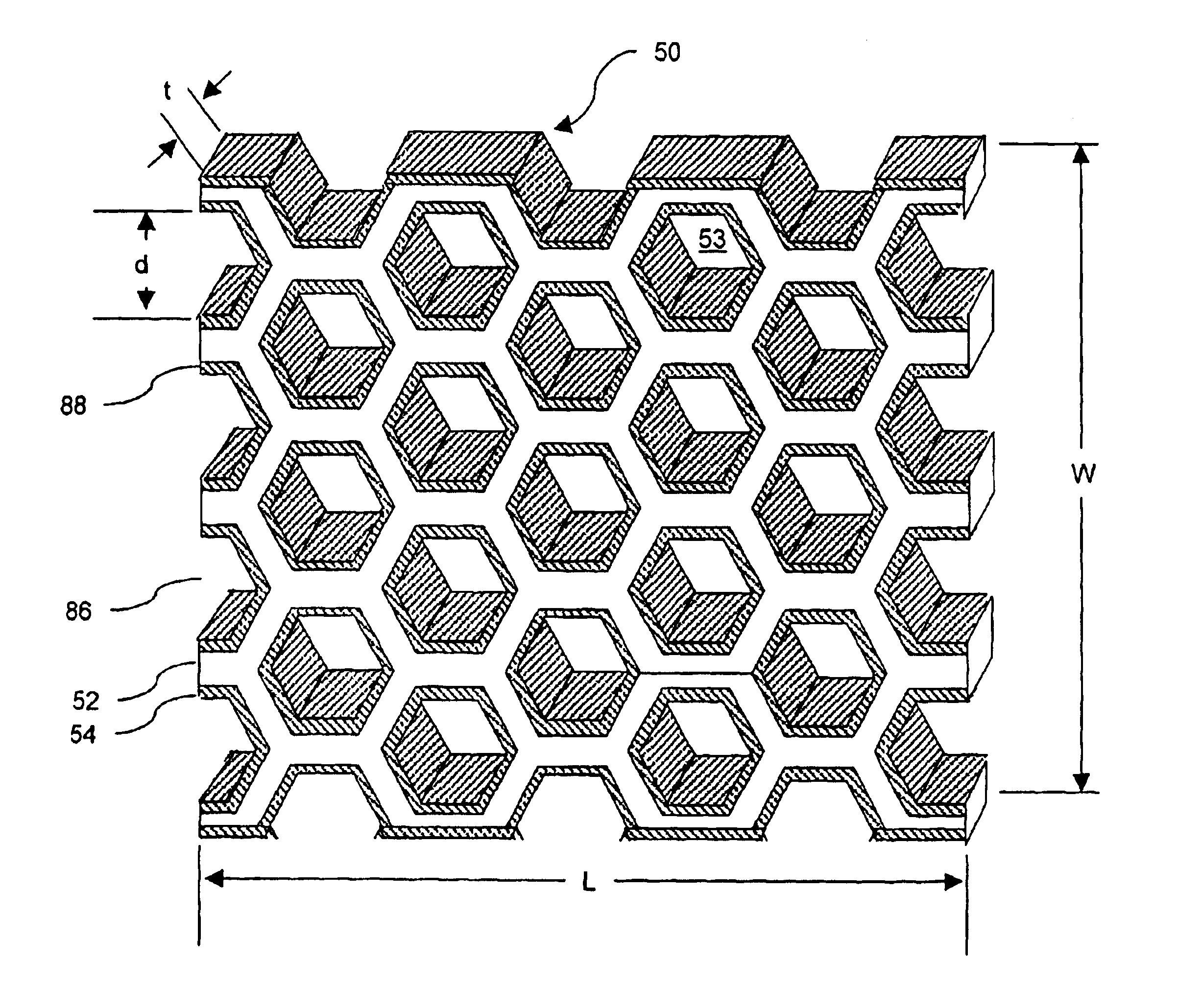
According to the present invention, honeycomb filters used for airflow and EMI shielding can have improved airflow and durability through the use of a metallized dielectric honeycomb substrate and a frameless filter design. Metallized dielectric honeycomb substrate utilized in a reduced frame design can also be used to provide even greater durability along with increased airflow.

FIG. 4 shows in perspective view, a cross-section of one embodiment of a metallized dielectric honeycomb filter 50. The metallized dielectric honeycomb filter 50 includes a dielectric honeycomb substrate 52 and a conductive layer 54. As used herein, the term honeycomb refers to a two-dimensional array of apertures of arbitrary cross-section. The aperture cross-section can be any shape, such as hexagonal, circular, elliptical, square, rectangular, triangular, rhomboidal, or other, and combinations thereof. The dielectric honeycomb substrate 52 is selected to provide significantly improved resiliency as compar...


PUM


Abstract

Disclosed are methods and apparatus for improving the resiliency and airflow through a honeycomb air vent filter while providing EMI shielding. In one embodiment, the honeycomb can be manufactured from a dielectric (e.g., plastic) substrate to provide improved resistance to deformation as compared to conventional aluminum honeycomb. The dielectric honeycomb substrate is metallized to provide EMI shielding capability. The metallized honeycomb substrate is cut slightly oversize to fit an opening in an electronic enclosure, which results in elastic deformation of resilient perimeter spring fingers that are used to hold the metallized dielectric honeycomb in place and provide electrical conductivity between the metallized dielectric substrate and the enclosure, thereby eliminating the use of a frame. In another embodiment, additional conductive layers can be added to the metallized dielectric honeycomb. In yet another embodiment, the metallized dielectric honeycomb substrate can be utilized in a framed configuration to provide improved durability.

Description

FIELD OF THE INVENTIONThis invention relates to methods of manufacturing electromagnetic interference (“EMI”) shields and the EMI shields produced thereby.BACKGROUND OF THE INVENTIONAs used herein, the term EMI should be considered to refer generally to both EMI and radio frequency interference (“RFI”) emissions, and the term electromagnetic should be considered to refer generally to electromagnetic and radio frequency.During normal operation, electronic equipment generates undesirable electromagnetic energy that can interfere with the operation of proximately located electronic equipment due to EMI transmission by radiation and conduction. The electromagnetic energy can be of a wide range of wavelengths and frequencies. To minimize the problems associated with EMI, sources of undesirable electromagnetic energy may be shielded and electrically grounded. Shielding is designed to prevent both ingress and egress of electromagnetic energy relative to a housing or other enclosure in whic...

Claims


Application Information

Patent Timeline
IPC IPC(8): H05K9/00
CPCH05K9/0041H05K9/00
Inventor LAMBERT, MICHAELMCFADDEN, JEFFVAN HAASTER, PHILIP
Owner LAIRD TECH INC
Why Eureka
Try Eureka