Electronic apparatus

a shielding box and electronic equipment technology, applied in the direction of electrical apparatus casings/cabinets/drawers, fixed connections, coupling device connections, etc., can solve the problems of /b> causing a large radiation noise on transmission and reception of high frequency signals, radiation noise leakage more or less, and reducing radiation noise leakage, and reducing the space in the shielding box without impairing the freedom of arrangement

Inactive Publication Date: 2005-03-22
CANON KK
View PDF6 Cites 10 Cited by
  • Summary
  • Abstract
  • Description
  • Claims
  • Application Information

AI Technical Summary

Benefits of technology

An object of the present invention is to reduce radiation noise leakage through an opening in a shielding box without decreasing the space in the shielding box without impairing freedom for arrangement of the printed circuit or the like without using an additional part. Another object of the present invention is to decrease radiation noise caused by common-mode current in the cable.

Problems solved by technology

However, the high frequency for the digital signal tends to cause radiation noise to result in malfunction of a separate electronic apparatus.
Cable 32 also produces much radiation noise on transmission and reception of high frequency signals.
However, radiation noise leaks out more or less through aperture 31.
This necessitates a larger space of the shielding box, which does not meet the recent demand for miniaturization of electronic apparatuses.
The variation of height of the cable can cause variation of the radiation noise level.
A slight deviation in height of the cable by conveyance of the electronic apparatus will cause variation of the produced radiation noise level.

Method used


Image

  • Electronic apparatus
  • Electronic apparatus
  • Electronic apparatus

Examples


example 1

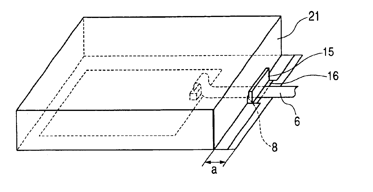
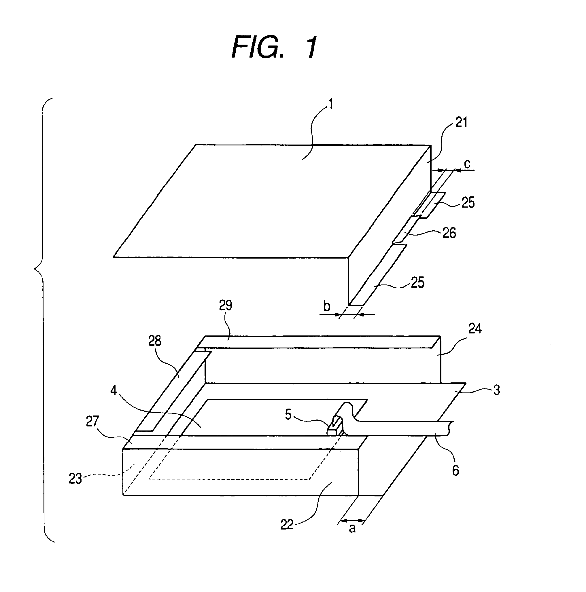
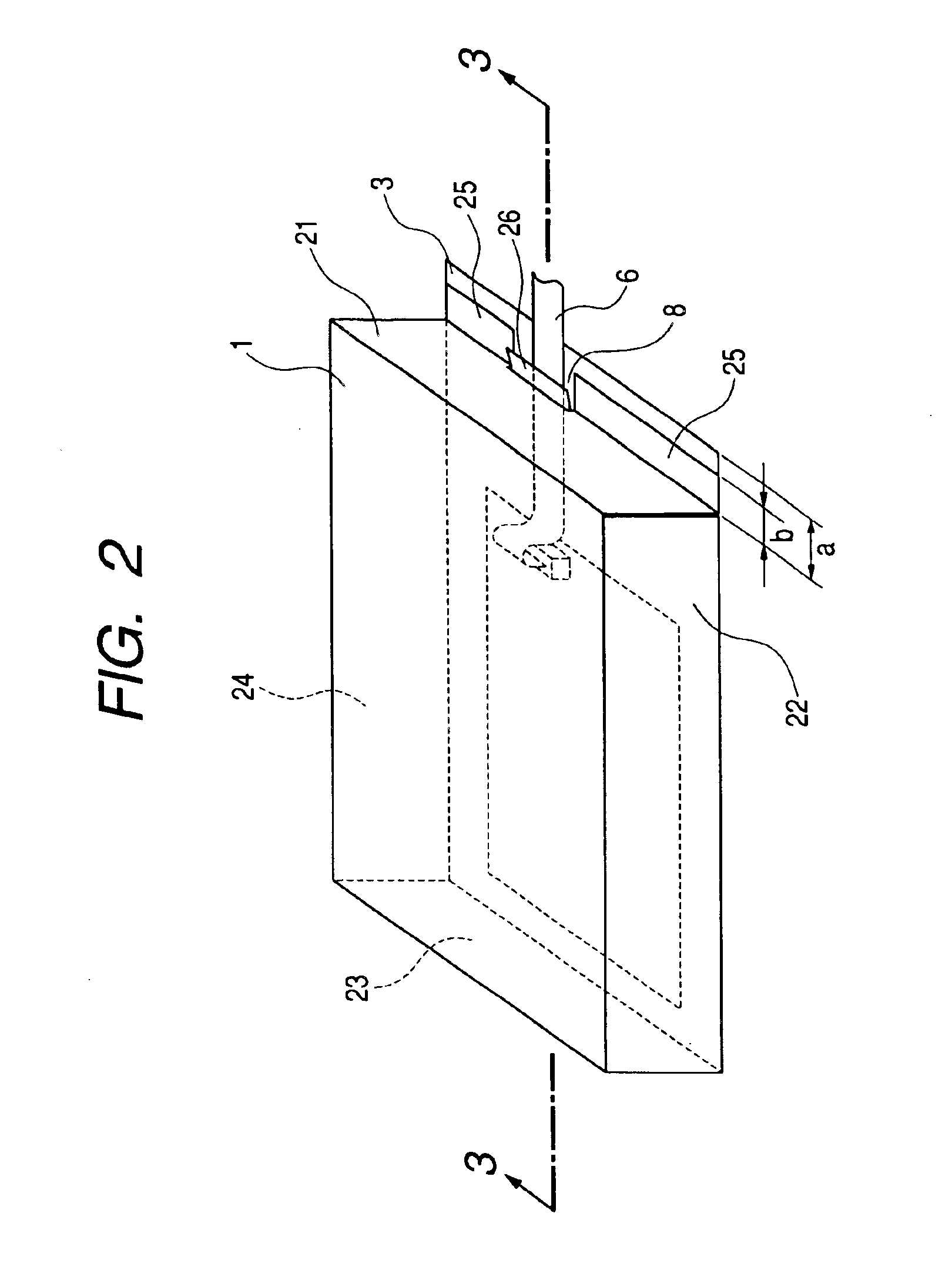
FIGS. 1 to 3 illustrate Example 1 of the present invention. The shielding box is comprised of top cover 1, bottom metal plate 3, and side plates 21,22,23 and 24. FIG. 1 is a perspective view of an exploded shielding box, showing a metal plate comprised integrally of top cover 1 and side plate 21 separated from the main body of the shielding box comprised of bottom metal plate 3 and side plates 22,23 and 24.

Printed circuit board 4 is placed with interposition of spacer 7 mentioned later on bottom metal plate 3 of the shielding box. The printed circuit board is connected through connector 5 to cable 6. Cable 6 is led out through side plate 21. Bottom metal plate 3 projects out of the shielding box in length a in the lead-out direction of cable 6, namely perpendicularly to side plate 21. The metal plate comprised integrally of top cover 1 and side plate 21 of the shielding box is fixed by screws securely to the inwardly bent top margins 27, 28 and 29 of side plates 22,23 and 24 and to ...

experiment 1

(Experiment 1)

An electronic apparatus containing a shielding box shown in FIGS. 1-3 was prepared, and the radiation noise was measured. The prepared shielding box is in a shape of a rectangular solid, having a size of 250 mm long, 300 mm wide, and 70 mm high. Top cover 1, and side plates 21,22,23 and 24 have a thickness of 1 mm. The length a of the projection of bottom metal plate 3 is 20 mm, the length b of tab 25 of side plate 21 is 10 mm, and the length d of tab 26 of side plate 21 is 10 mm. The width of tab 26 (i.e., the width of aperture 8) is 50 mm, and the height of aperture 8 is 10 mm. The metal plate comprised integrally of top cover 1 and side plate 21 is fixed at tab 25 of length b to bottom metal plate 3 by screws (not shown in the drawings). Top cover 1 is fixed to inwardly bent top margins 27, 28 and 29 of side plates 22, 23 and 24 by screws. Printed circuit board 4 is a digital substrate of 220 mm long and 270 mm wide driven by high frequency of 20 MHz, and is placed ...

example 2

FIGS. 6-8 show Example 2 of the present invention. FIG. 6 is a perspective view of the shielding box, having top cover 1 and side plate 21 separated from the main body comprised of bottom metal plate 3 and side plates 22,23 and 24. FIG. 7 is a perspective view of the shielding box, having top cover 1 and side plate 21 attached to the main body comprised of bottom metal plate 3 and side plates 22, 23 and 24. FIG. 8 is a perspective view of the shielding box placed on casing body 9.

The lower end of side plate 21 is notched at the middle portion thereof to form rectangular notch 10. This rectangular notch and bottom metal plate 3 form aperture 8. Elastic metal member 11 for closing aperture 8 is fixed to side plate 21 by screws 13. The numerals 12a and 12b denote holes formed through the elastic member and side plate 21 for insertion screws 13. Elastic member 11 has at least a size sufficient to cover aperture 8, and is warped in a U-shape at the lower end.

Cable 6 is pressed at apertur...


PUM


Abstract

An electronic apparatus is provided which causes less radiation noise leakage through an aperture with a shielding box in a compact size. The apparatus has a shielding box encasing a printed circuit board connected to a cable. The shielding box has a cable-regulating portion which seals the aperture of the shielding box for leading out the cable connected to the printed board and presses the cable against the bottom plate of the shielding box. Thereby the radiation noise caused by common-mode current in the cable is also reduced.

Description

BACKGROUND OF THE INVENTION1. Field of the InventionThe present invention relates to a shielding box for encasing a printed circuit board connected to a cable, particularly to a shielding box for decrease of radiation noise leakage through an aperture for leading out the cable and decrease of radiation noise generated by the cable itself. The present invention relates also to an electronic apparatus having the shielding box, and a method of fixing the cable.2. Related Background ArtIn recent years, the clock frequency of digital circuits of electronic apparatuses is being made higher and higher. However, the high frequency for the digital signal tends to cause radiation noise to result in malfunction of a separate electronic apparatus. Therefore, the radiation noise emission is an object of the regulation.For decrease of the radiation noise, a shielding box shown in FIG. 13 is known for encasing a printed circuit board to shield the radiation noise emission. In FIG. 13, the numeral ...

Claims


Application Information

Patent Timeline
Patent Type & Authority Patents(United States)
IPC IPC(8): H01R13/658H01R13/58H05K7/00H01R12/59H01R13/6596H01R13/719H05K9/00
CPCH01R12/59H01R13/6596H01R13/5816H01R13/719
Inventor OTAKI, TORU
Owner CANON KK
Why Eureka
Try Eureka