Integrated microchip design

Inactive Publication Date: 2005-03-22
INTEGENX
View PDF8 Cites 90 Cited by
  • Summary
  • Abstract
  • Description
  • Claims
  • Application Information

AI Technical Summary

Benefits of technology

In a second embodiment, the chips are separated and rejoined to establish/disrupt channel connection. The basic design of the microchip is still the same as in the first embodiment. The ‘jogging’ approach reduces wear at the joining edges. Specific surface coatings for the joining edges that help prevent leakage and keep liquid in the capillary channels are d

Problems solved by technology

Sliding can also disrupt chan

Method used


Image

  • Integrated microchip design
  • Integrated microchip design
  • Integrated microchip design

Examples


Embodiment Construction

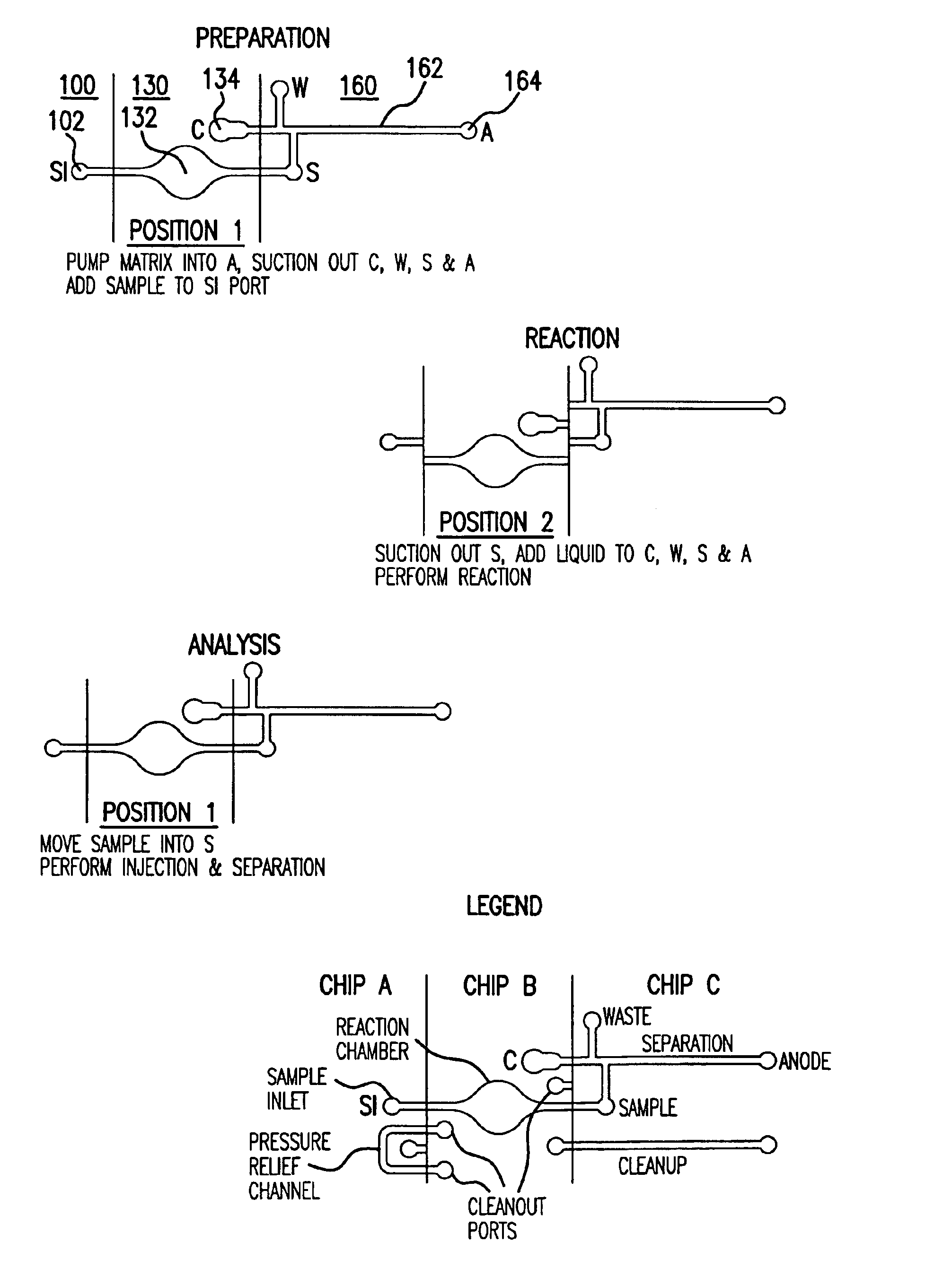
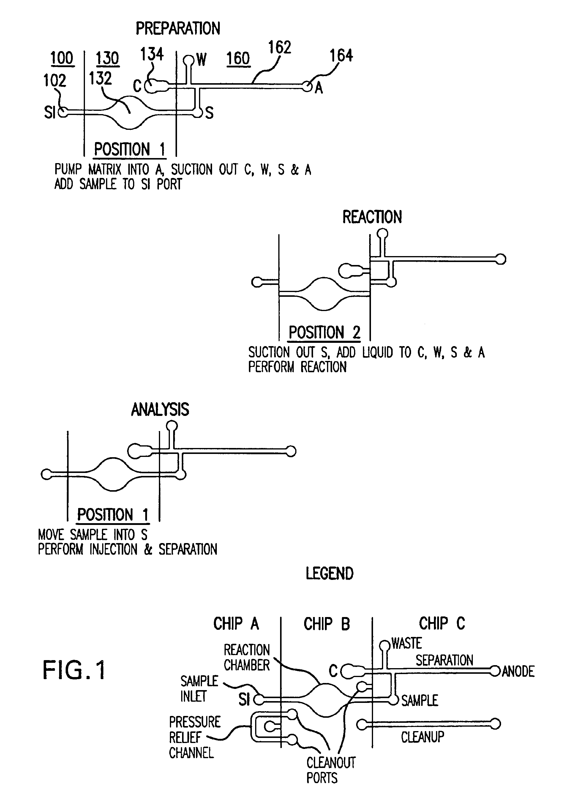
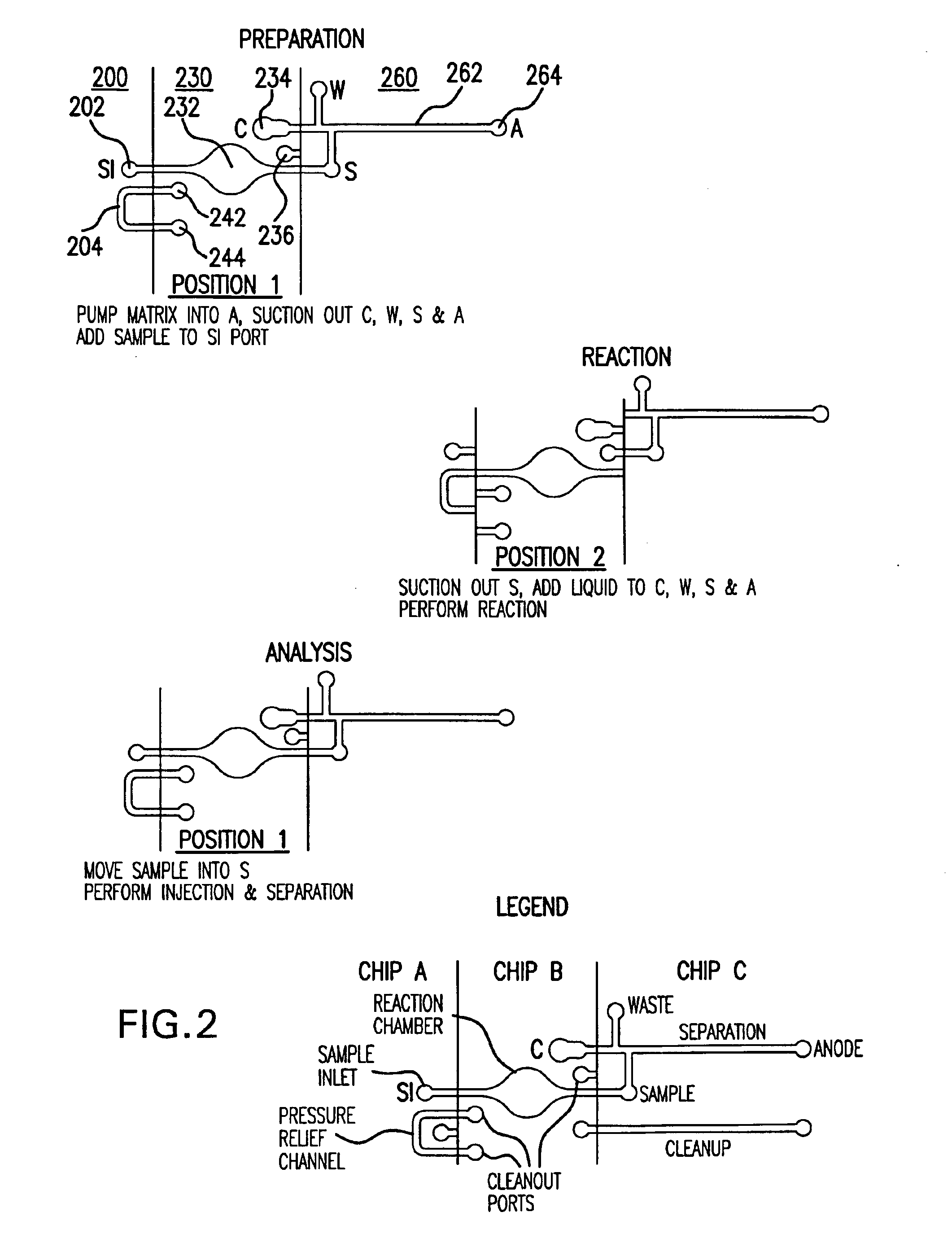
The present invention provides microfluidic devices and systems for integration and / or isolation of various functions in a microchip system and methods for using the same.

The present invention will now be described with regard to the accompanying drawings which assist in illustrating various features of the invention. However, it should be appreciated that the drawings do not constitute limitations on the scope of the present invention. Throughout the drawings, like numbered items represent same elements of the invention. For the sake of brevity and clarity, most figures show only one set of microfluidic channels; however, it should be appreciated that typical microfluidic devices comprise multiple sets of microfluidic channels.

In one aspect, the integration and / or isolation of the various functions in a microchip system is achieved using a sliding linear approach. According to one particular embodiment of the current invention, the integration and / or isolation of various functions ...


PUM


Abstract

Structures and methods that facilitate integration and/or isolation of various functions in a microchip system are disclosed. In one embodiment, the integration of the functions is by a multi-chip, sliding linear valve approach. The chips are in continued physical contact. In a second embodiment, the chips are separated and rejoined when they are moved to the preferred position. Surface coating of the joining edges helps prevent leakage and keeps liquid in the capillary channels for both embodiments. Another embodiment relates to miniature valves. Several designs were disclosed, including the linear, edge-contact sliding valve approach. Method to fabricate very small, high aspect ratio holes in glass was also disclosed, which facilitates the above embodiments.

Description

FIELD OF THE INVENTIONThe present invention relates generally to microfluidic devices and systems and methods for using the same. More particularly, the present invention provides structures and methods that facilitate integration and / or isolation of various functions in a microchip systemBACKGROUND OF THE INVENTIONMicrofluidics consist of using microchannels instead of test tubes or microplates to carry out analyses and reactions. These microchannels or microcircuits are fabricated into silicon, quartz, glass, ceramics or plastic. The size of these channels is on the order of micrometers, while the reaction volumes are on the order of nanoliters or microliters. The principle of a microfluidic device is to guide reaction media containing reagents and samples, through zones which correspond to the different steps of the protocol. The integration into a single system of reactors, sample treatment, separation, and miniature detection systems into these microfluidic systems allows the a...

Claims


Application Information

Patent Timeline
IPC IPC(8): B01L3/00
CPCB01L3/502715B01L3/502738B01L2200/027B01L2200/10B01L2300/0861G01N27/44791B01L2400/0622B01L2400/0644B01L2400/065G01N27/44743B01L2400/0487
Inventor ROACH, DAVID JOHNNI, JINGBLAGA, IULIU-IOANSALVEN, OWEJOVANOVICH, STEVAN BOGDAN
Owner INTEGENX
Why Eureka
Try Eureka