Schmitt trigger circuit with adjustable trip point voltages

a trigger circuit and trip point technology, applied in the field of digital circuits and electronics, can solve the problems of not being recognized at all, unduly delayed actual input voltage transition at the output, and noisy operation of digital systems

Inactive Publication Date: 2005-03-22
ALTERA CORP
View PDF5 Cites 42 Cited by
  • Summary
  • Abstract
  • Description
  • Claims
  • Application Information

AI Technical Summary

Problems solved by technology

Ideally, digital signals do not depart significantly from their expected voltage levels, but in practice digital systems usually operate under noisy conditions where there are signals unrelated to the signal of interest.
In some cases, the noise level can be so large that false switching occurs, resulting in a meta-stable environment in which a digital low signal appears as a digital high signal, or vice-versa.
However, if the upper trip point voltage is set too high and / or the lower trip point voltage is set too low, actual input voltage transitions may be unduly delayed at the output or, worse yet, not recognized at all.
If a Schmitt trigger circuit is designed to operate for a given VCC voltage, when the value of VCC changes by a significant amount, the hysteresis voltage and specific trip point voltage levels may no longer satisfy desired noise margin, delay, and input recognition criteria.

Method used


Image

  • Schmitt trigger circuit with adjustable trip point voltages
  • Schmitt trigger circuit with adjustable trip point voltages
  • Schmitt trigger circuit with adjustable trip point voltages

Examples


Embodiment Construction

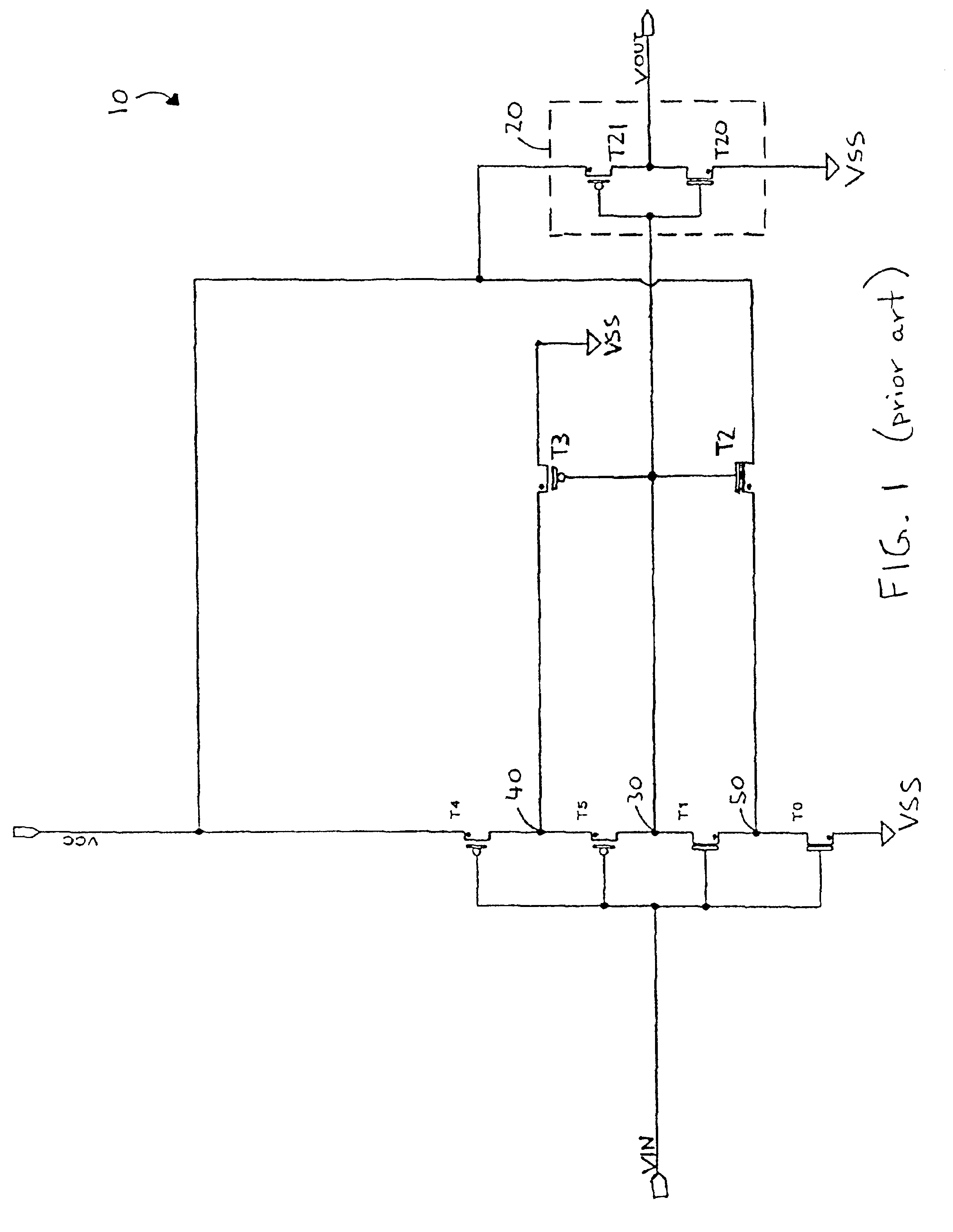
[0019]FIG. 1 is a circuit diagram of a prior art Schmitt trigger circuit 10 implemented using CMOS (complementary metal-oxide semiconductor) technology in which n-channel (NMOS) and p-channel (PMOS) metal oxide semiconductor field-effect transistors are combined, typically on a common substrate. CMOS-based implementations of Schmitt triggers are generally advantageous since they provide a high input impedance, can be readily designed to have threshold voltages that are roughly symmetrical to one-half the supply voltage, consume low power, and are easily integrated with other CMOS circuitry. CMOS Schmitt Triggers are discussed, for example, in “CMOS Schmitt Trigger B A Uniquely Versatile Design Component”, Fairchild Semiconductor Application Note 140 (June 1975) and in Kuang et al., “PD / SOI CMOS Schmitt Trigger Circuits with Controllable Hysteresis”, International Symposium on VLSI Technology, Systems, and Applications, Hsinchu, Taiwan (April 2001), and the contents of each are incor...


PUM


Abstract

A Schmitt trigger circuit has an adjustable hysteresis characteristic by providing a plurality of feedback circuits that differently affect at least one, and preferably both, of the circuit's upper trip point level and lower trip point level. The upper trip point level can be adjusted by selecting a desired feedback circuit from a first set of feedback circuits, and / or the lower trip point level can be adjusted by selecting a desired feedback circuit from a second set of feedback circuits. Feedback circuit selection is achieved by one or more control signals that may be programmable. The hysteresis characteristic can be adjusted to meet desired noise margin, delay, and input recognition criteria at different VCC levels. The Schmitt trigger circuit may be a CMOS Schmitt trigger with two input stage NMOS, two input stage PMOS transistors, a first set of NMOS feedback circuits, and a second set of PMOS feedback circuits.

Description

FIELD OF INVENTION[0002]The present invention relates generally to the fields of digital circuits and electronics. More particularly, it relates to a Schmitt trigger circuit that has adjustable trip point voltages and that is suitable for use with different power supply signal levels.BACKGROUND OF THE INVENTION[0003]In a digital system, signals typically take on one of two values, i.e., high or low, depending on the voltage level of the signal. Ideally, digital signals do not depart significantly from their expected voltage levels, but in practice digital systems usually operate under noisy conditions where there are signals unrelated to the signal of interest. In some cases, the noise level can be so large that false switching occurs, resulting in a meta-stable environment in which a digital low signal appears as a digital high signal, or vice-versa.[0004]A common approach to eliminating or reducing the effects of noise in a digital system is to employ logic circuitry in which the ...

Claims


Application Information

Patent Timeline
Patent Type & Authority Patents(United States)
IPC IPC(8): H03K3/3565H03K3/00
CPCH03K3/3565
Inventor CHANG, TZUNG-CHINSUNG, CHIAKANGNGUYEN, KHAIHUANG, JOSEPHWANG, BONNIECHONG, YANWANG, XIAOBAOPAN, PHILIPRANGAN, GOPINATHKIM, IN WHAN
Owner ALTERA CORP
Why Eureka
Try Eureka