Method for evaluating image formation performance

a technology of image formation and performance, applied in the direction of polarising elements, printing, instruments, etc., can solve the problems of critical defect in ultra high accuracy of optical systems, aberration occurring due to birefringence of lens materials, etc., to achieve sufficient accuracy, accurate results, and easy to perform

Inactive Publication Date: 2005-03-22
NIKON CORP
View PDF45 Cites 81 Cited by
  • Summary
  • Abstract
  • Description
  • Claims
  • Application Information

AI Technical Summary

Problems solved by technology

The aberration occurring due to birefringence of a lens material is critically defective to an optical system with ultra high accuracy such as a projection optical system used to manufacture an electronic device.

Method used


Image

  • Method for evaluating image formation performance
  • Method for evaluating image formation performance
  • Method for evaluating image formation performance

Examples


first embodiment

[First Embodiment]

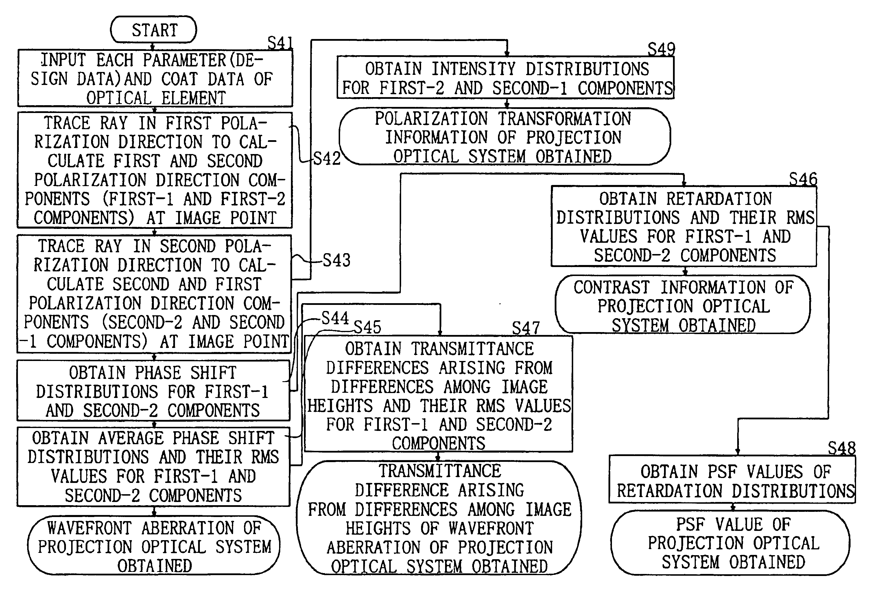
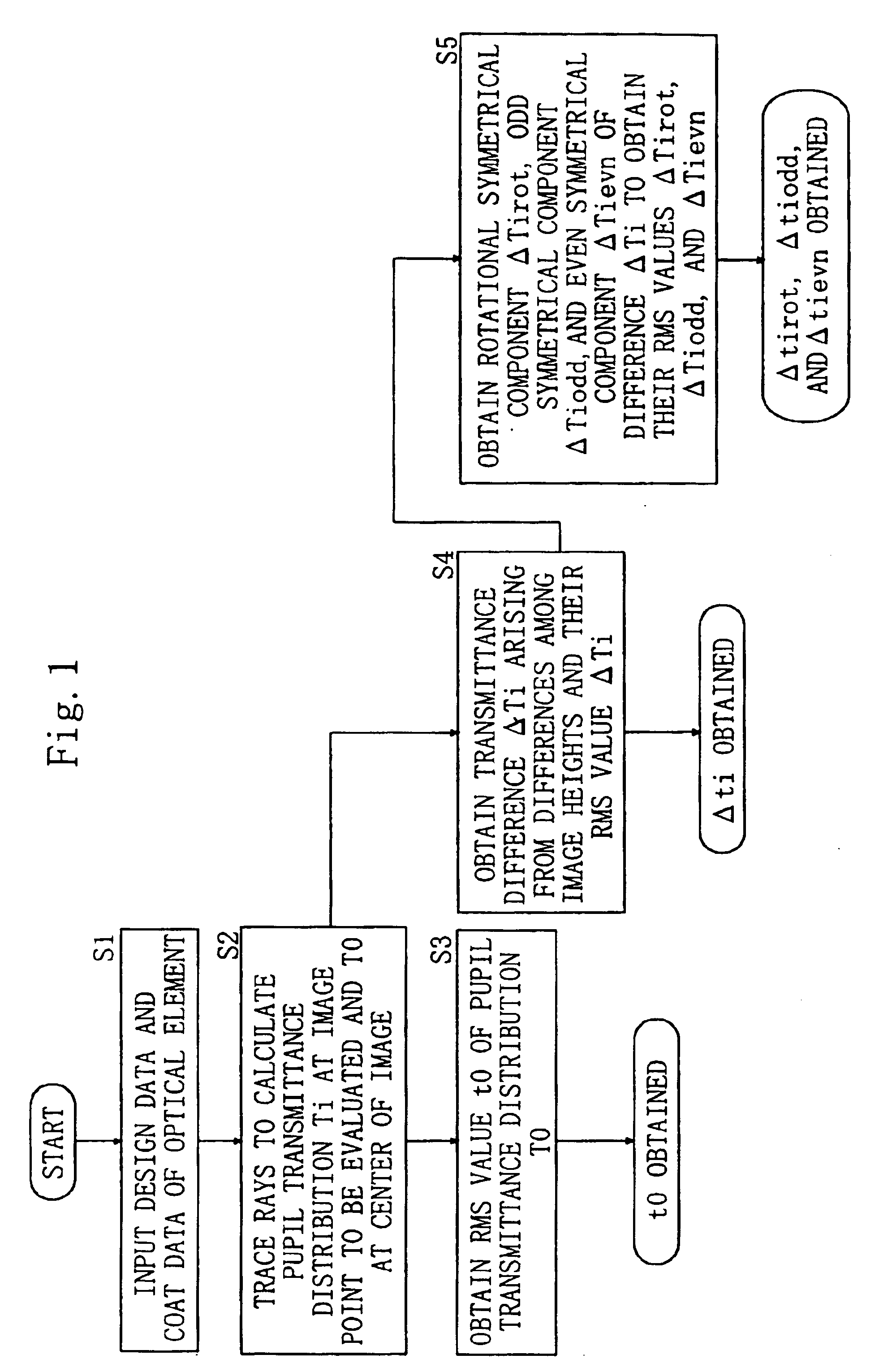
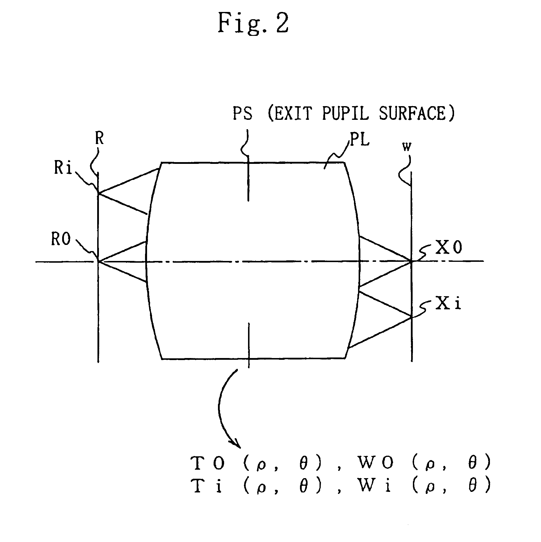
First of all, with reference to FIG. 1, FIG. 2, FIG. 3, and FIG. 4, a first embodiment of the present invention will be described.

According to the first embodiment, image formation performance of an optical system is evaluated using two main evaluation indexes (an evaluation index according to a transmittance and an evaluation index according to a phase shift).

In addition, the first embodiment is suitable for evaluating a projection optical system applied to an exposure apparatus. Thus, the following description is to be made on the assumption that the projection optical system is the evaluation object. Since a projection optical system has many optical elements such as lenses and reflection surfaces, calculations required for the evaluation are often complex. Thus, the procedure for obtaining each evaluation index that will be described in the following is assumed to be executed by a computer.

In the Specification, “average” and “RMS” are defined as follows.

An aver...

second embodiment

[Second Embodiment]

Next, with reference to FIG. 5, a second embodiment of the present invention will be described.

In the second embodiment, the first embodiment is applied to manufacturing (in particular, step S202 (coat allocation) that will be described later) of a projection optical system used for an exposure apparatus.

Next, the second embodiment will be described on the assumption that a projection optical system to be manufactured is a refractive projection optical system and that optical elements that compose the refractive projection optical system are a plurality of lenses. However, when a reflection type or reflection-refractive type projection optical system that has a reflection surface is manufactured, the present invention can be applied likewise (in this case, data of reflection surfaces is added to lens data).

FIG. 5 is a flow chart showing a procedure of the second embodiment.

(Step S100)

At step S100, an optical design for a projection optical system is performed so t...

third embodiment

[Third Embodiment]

Next, with reference to FIG. 6, a third embodiment of the present invention will be described.

In the third embodiment, as example 1 to example 4, the first embodiment is applied to a lens design (lens correction) of an optical system.

FIG. 6 is a table showing correction targets, evaluation indexes, and optimization parameters in the lens design (lens correction) of example 1 to example 4 according to the third embodiment.


PUM

PropertyMeasurementUnit
wavelengthsaaaaaaaaaa
wavelengthaaaaaaaaaa
wave lengthaaaaaaaaaa

Abstract

The present invention accomplishes an evaluation of image formation performance in which the influence of a coat is accurately reflected. According to the present invention, for the evaluation of image formation performance of an optical system obtained is a pupil transmittance distribution (a distribution of light transmittance on an exit pupil surface) of a light beam that enters an image point to be evaluated of the optical system. At least one of a rotational symmetrical component, an odd symmetrical component, and an even symmetrical component is extracted from the obtained pupil transmittance distribution as an evaluation index.

Description

BACKGROUND OF THE INVENTION1. Field of the InventionThe present invention relates to an evaluating method for image formation performance of optical systems such as a projection optical system and an observation optical system used in photolithography, a coat designing method according to the evaluation, an optical system designing method according to the evaluation, an optical system, an optical system manufacturing method, a design program, a computer readable storage medium, a projection exposure apparatus, and a projection exposure method.In addition, the present invention relates to a projection optical system, a manufacturing method thereof, and an exposure apparatus having the projection optical system, in particular, to a projection optical system suitable for an exposure apparatus used when microdevices such as a semiconductor device and a liquid crystal display device are manufactured by a photolithography processing.2. Description of the Related ArtWhen a fine pattern of ...

Claims


Application Information

Patent Timeline
Patent Type & Authority Patents(United States)
IPC IPC(8): G02B27/00G03F7/20G02B7/36
CPCG02B7/36G02B27/0012G03F7/70966G03F7/70591G03F7/706G02B27/0043
Inventor OZAWA, TOSHIHIKO
Owner NIKON CORP
Why Eureka
Try Eureka