Enhanced spur cable circuit protection device and method for its implementation

a protection device and spur cable technology, applied in pneumatic programme control, pneumatic control, instruments, etc., can solve the problems of failure of any device, circuitry overheating and self-destructing, and limited available power

Inactive Publication Date: 2005-03-22
RELCOM
View PDF20 Cites 4 Cited by
  • Summary
  • Abstract
  • Description
  • Claims
  • Application Information

AI Technical Summary

Benefits of technology

The circuit of the invention provides protection for both a spur circuit and the network while allowing other spurs on the network to continue operation and is applicable to both FF and ASi type networks as well as any other type of data and power network. A control circuit monitors a current limiter coupled to each spur circuit. If the spur circuit goes into an overcurrent condition for a preset period of time, the control circuit turns it off. After a second period of time has elapsed, the control circuit turns the current limiter back on permitting current to flow in the spur once again while continuing to monitor the current limiter.

Problems solved by technology

Any short or overcurrent condition on the spur cable results in the failure of any devices on that spur but the rest of the spurs, with their associated devices and the network, continue to operate normally as long as there is sufficient current for the trip point on the protection circuit.
To raise the current trip point limit on a circuit such as disclosed in U.S. Pat. No. 6,366,437, could cause the circuitry to overheat and self-destruct during a sustained short circuit because of the amount of power available on the network.
Moreover, on some FF networks, especially those used for intrinsically safe installations, the available power is limited in order to prevent a spark from causing an explosion in the hazardous area.
A short on the spur in this situation would not prevent failure of the entire segment.

Method used


Image

  • Enhanced spur cable circuit protection device and method for its implementation
  • Enhanced spur cable circuit protection device and method for its implementation
  • Enhanced spur cable circuit protection device and method for its implementation

Examples


Embodiment Construction

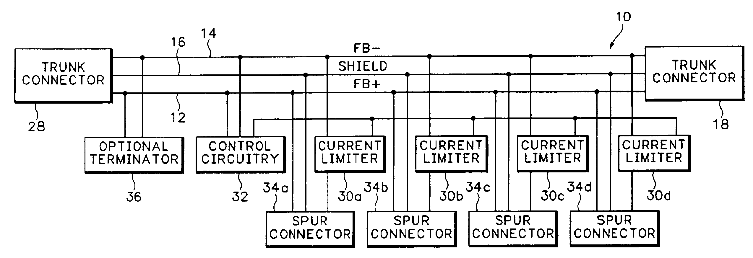
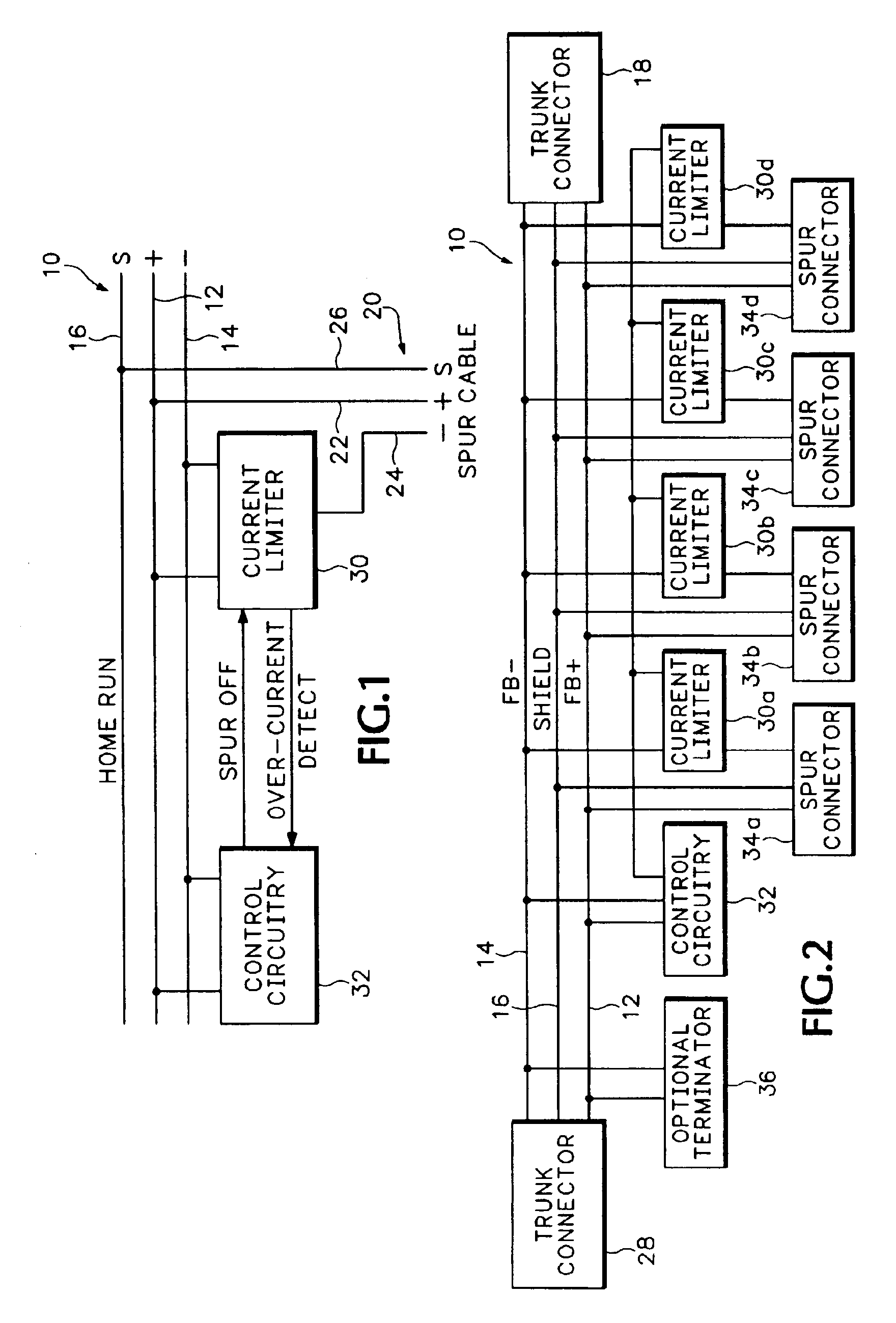
Referring to FIG. 1, a fieldbus network includes a “home run” cable or trunk line 10 which comprises a positive lead 12, a negative lead 14 and a shield 16. Connected to the home run network 10 are one or more spur cables 20. Each spur cable includes a positive line 22, a negative line 24 and a shield 26.

The home run 10 is a trunk line of the conventional type described above, that is, it is either an ASi network or a foundation fieldbus network or some similar network. As such, the positive and negative wires 12 and 14 carry both power and data. Coupled in parallel with the home run 10 and the spur cable 20 is a protection circuit which includes a current limiter 30 coupled to control circuitry 32. In FIG. 1, the current limiter 30 is coupled in-line with the negative lead 24 of the spur cable 20. In the event of an overcurrent condition that persists for a first time period, the current limiter 30 turns off current in the spur cable 20 thus serving as a protection circuit for the ...


PUM


Abstract

The circuit of the invention provides protection for both a spur circuit and the network while allowing other spurs on the network to continue operation and is applicable to any type of fieldbus network including both FF and ASi type networks. A control circuit monitors a current limiter coupled to each spur circuit. If the spur circuit goes into an overcurrent condition for a preset period of time, the control circuit turns it off. After a second period of time has elapsed, the control circuit turns the current limiter back on permitting current to flow in the spur once again while continuing to monitor the current limiter.

Description

STATEMENT REGARDING FEDERALLY SPONSORED RESEARCH OR DEVELOPMENTNot applicable.REFERENCE TO SEQUENCE LISTING, A TABLE, OR A COMPUTER PROGRAM LISTING COMPACT DISK APPENDIXNot applicable.BACKGROUND OF THE INVENTIONThe present invention relates to a fieldbus network and, more particularly, to a current limiter to protect a fieldbus network from an electrical short in a spur cable or a device attached to a spur cable.In a typical industrial plant application, sensors measure position, motion, pressure, temperature, flow, and other parameters related to the operation of process machinery and activities. Actuators, such as valves and motor controllers, control the operation of the machinery and process activities. The sensors and actuators are remotely located from the human and computerized controllers which gather information from the sensors and direct operation of the actuators. A communication network links the controllers with the sensors and actuators located in the field.Heretofore...

Claims


Application Information

Patent Timeline
Patent Type & Authority Patents(United States)
IPC IPC(8): G05B19/00G05B19/44H02H9/02H04L29/06H02H3/02H02H3/04H04L29/08
CPCG05B19/44H04L67/12H04L29/06H02H9/025H02H3/042Y04S40/18H04L9/40
Inventor STRAUSER, MICHAELGRAUBE, MARISLOMMEN, DANA
Owner RELCOM
Why Eureka
Try Eureka