Fiber-type optical coupler with slanting Bragg diffraction gratings and optical parts and apparatuses using the same

a fiber-type, optical coupler technology, applied in the direction of optics, optical waveguide light guides, instruments, etc., can solve the problems of increasing optical insertion loss, inability to be ignored, and inability to help, so as to achieve high reliability, stable and economical

Inactive Publication Date: 2005-03-22
NEC CORP
View PDF7 Cites 17 Cited by
  • Summary
  • Abstract
  • Description
  • Claims
  • Application Information

AI Technical Summary

Benefits of technology

Therefore, an object of the present invention is to provide a fiber-type optical coupler that is an optical device for implementing an advanced optical communication system utilizing wavelengths as a resource, optical parts of which configuration using this coupler is highly reliable, stable and economical and a method of manufacturing them as well as various optical apparatuses utilizing this fiber-type optical coupler.

Problems solved by technology

And one of technological challenges of the optical parts is that the star coupler sufficiently functions in a descending distribution system but ascending signals from the subscriber lines can only collect power of 1 / N at the station in the ascending multiplexing system, which occupies a major portion of signal transmission loss, and so an optical multiplexer of N:1 capable of optical multiplexing with no loss is anticipated.
However, the devices have common faults, that is, they are sensitive to temperature change, increase in optical insertion loss due to connection between the devices and optical fibers cannot be ignored, and they are expensive.
In addition, to embody the optical parts and apparatuses that require the nonreciprocal transmission property including the optical circulator, optical multiplexer with no loss, and optical transmission and reception module mentioned in the above prior art, it cannot be helped, considering the current technological level, to rely on a method of using Faraday polarization rotation effect of magneto-optic materials.
Thus, they must be configured by many discrete elements such as lenses and magneto-optic crystals so that they are too expensive and unstable to be practical.

Method used


Image

  • Fiber-type optical coupler with slanting Bragg diffraction gratings and optical parts and apparatuses using the same
  • Fiber-type optical coupler with slanting Bragg diffraction gratings and optical parts and apparatuses using the same
  • Fiber-type optical coupler with slanting Bragg diffraction gratings and optical parts and apparatuses using the same

Examples


third embodiment

Next, a further embodiment of the present invention will be described. Before that, further unique properties of basic components of the present invention will be described. This description will help understand the third embodiment and thereafter that utilize the unique properties.

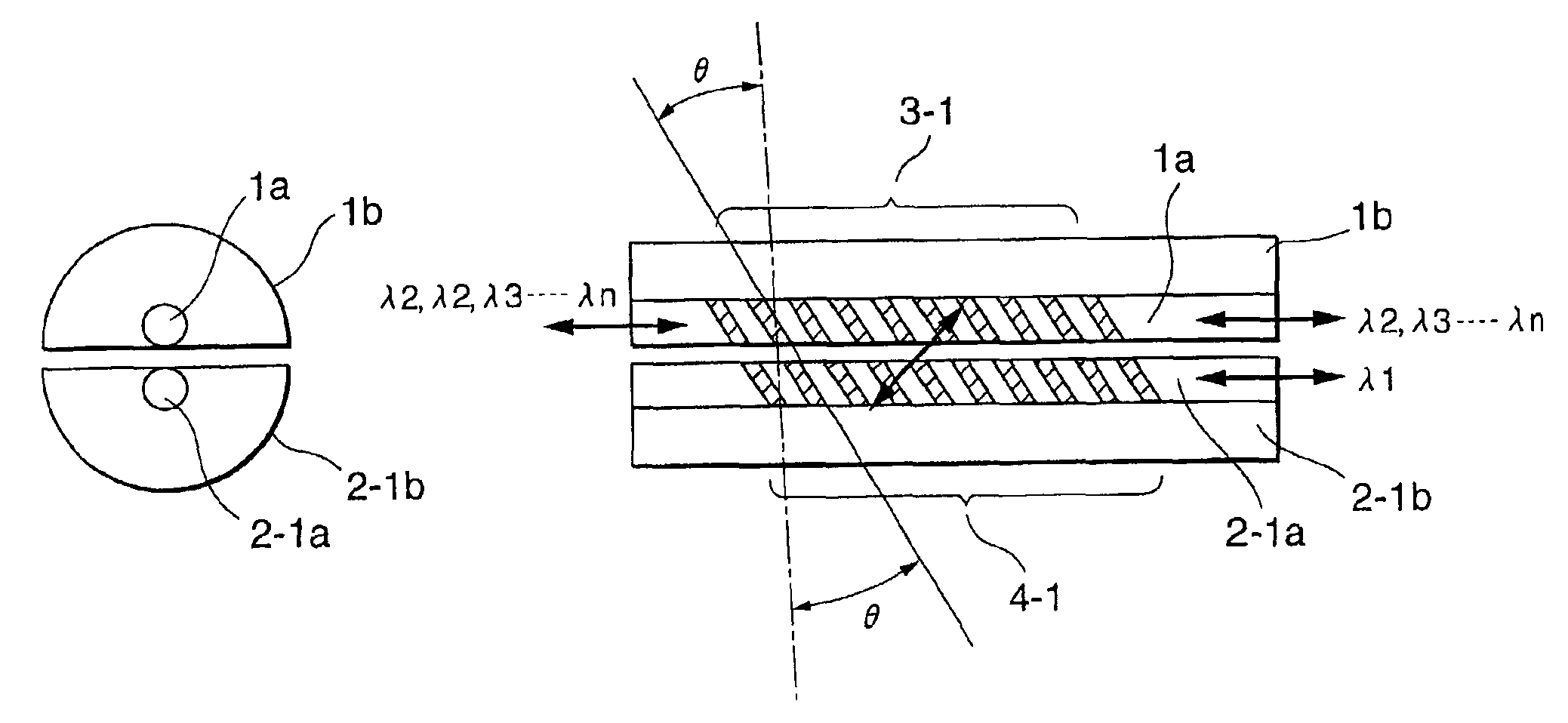
The basic components of the present invention are, so to speak, a set of Bragg diffraction optical couplers of configuration wherein two optical fibers forming a tilted Bragg grating in the core section are placed with their optical axes parallel and the respective cores close in the area forming mutual tilt gratings. In the placement related to a propagation direction of guided mode light and a tilt angle of the Bragg grating described in detail so far, this device causes Bragg diffraction coupling from the guided mode for letting it in from the left terminal of one primary optical fiber and advancing it rightward in the core section to the guided mode for also advancing it rightward in the other second ...

sixth embodiment

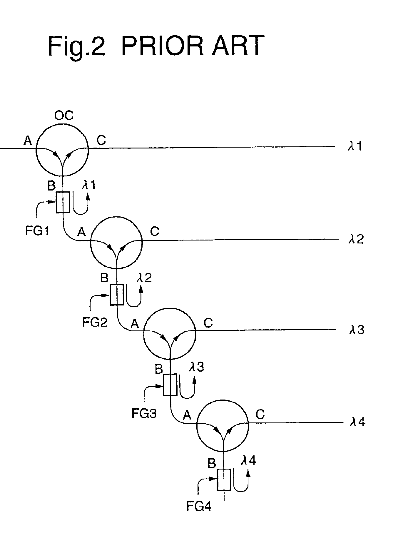
Next, an example of configuring an optical circulator is shown as the present invention. Here, an example of three ports is described. As for operation of a three-terminal circulator in principle, as shown in FIG. 2, it operates so that a signal inputted to the terminal A is outputted to the terminal B, an input signal to the terminal B is outputted to the terminal C, and an input signal to the terminal C is outputted to the terminal A.

If an optical circulator performing the same operation as this is implemented by utilizing the nonreciprocity of the Bragg diffraction optical coupler by the tilt grating of the present invention, it can be configured as shown in FIG. 17 as an example. 201, 202 and 203 in the drawing are Bragg diffraction optical couplers supported by two V-groove substrates on the topside and underside, where the left terminal of the upper optical fiber 204 of the Bragg diffraction optical coupler 201 is the input terminal A, the left terminal of the upper optical fi...


PUM


Abstract

A fiber-type optical coupler has two optical fibers including a core on which a slanting Bragg diffraction grating is formed and a first cladding and a second cladding bordered with a boundary plane close to the core. The two optical fibers are placed by approximating the boundary plane almost contacting the core, making respective optical axes almost parallel and also making slanting directions of the respective Bragg diffraction gratings almost parallel. A wave vector of the slanting Bragg diffraction grating is located in a plane made by a normal set up on the boundary plane almost contacting the core and the optical axis of the core, and an angle θ made by the wave vector and the optical axis is 0 degree<θ<90 degrees. In addition, a refractive index of the second cladding is lower than that of the first cladding.

Description

BACKGROUND OF THE INVENTION1. Field of the InventionThe present invention relates to an optical coupler, optical parts and an optical apparatuses utilizing the optical coupler and also a method of manufacturing the optical coupler.2. Description of the Prior ArtAn explosive increase in communication traffic is also expected in the future due to the advent of an Internet society. And implementation of a network capable of accommodating the increase in communication traffic, which is large-capacity, high-speed and inexpensive as to communication costs is required. A network technology meeting such requirements is an optical fiber communication technology. In order to allow large capacity, high speed and inexpensiveness in the optical fiber communication technology, it is necessary to develop a multiplexing technology of high density. While a time division multiplex technology, a wavelength division multiplex technology and combined use of them are thinkable as a method of multiplexing...

Claims


Application Information

Patent Timeline
Patent Type & Authority Patents(United States)
IPC IPC(8): G02B6/02G02B6/34G02B6/36G02B6/293
CPCG02B6/02085G02B6/02138G02B6/29334G02B6/3652G02B6/3636
Inventor OHTA, YOSHINORIURINO, YUTAKA
Owner NEC CORP
Why Eureka
Try Eureka