Method of manufacturing a fiber-type optical coupler with slanting bragg diffraction gratings
a technology of diffraction grating and fiber-type optical coupler, which is applied in the direction of optics, optical waveguide light guides, instruments, etc., can solve the problems of increasing optical insertion loss, inability to be ignored, and inability to help, so as to achieve high reliability, stable and economical
- Summary
- Abstract
- Description
- Claims
- Application Information
AI Technical Summary
Benefits of technology
Problems solved by technology
Method used
Image
Examples
first embodiment
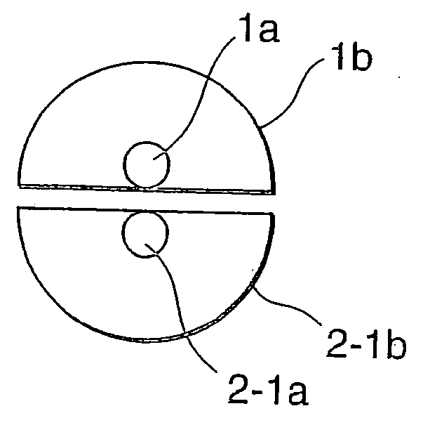
[0043] Referring to FIG. 3, the multiplexer-demultiplexer of the present invention comprises a principal optical fiber 1 and n pieces of branching fiber 2-1 to 2-n, and Bragg gratings 3-1 to 3-n formed tilting to an optical axis are provided in cores at n locations partway in the direction of optical transmission of the principal optical fiber 1, and also Bragg gratings 4-1 to 4-n formed tilting to the optical axis are provided in the cores near one terminal of the branching fibers 2-1 to 2-n. Periods of the n pieces of tilt gratings Λ1, Λ2, Λ3, . . . Λn are all different.
[0044] And as shown in FIG. 4, the principal optical fiber 1 and the branching fibers 2-1 to 2-n are placed at areas forming the respective Bragg gratings in the optical axis direction with mutual optical axes parallel and the respective cores close. FIG. 4A shows a section view cut vertically to the optical axis and FIG. 4B shows a section view cut along the optical axis. As shown in FIG. 4A, a cladding 1b of the ...
second embodiment
[0066] Next, a fiber optical amplifier of the present invention will be described by referring to the drawings. FIG. 10 is an embodiment where in the present invention is implemented to a fiber optical direct amplifier, and it comprises an optical amplification rare-earth dope fiber 70 containing rare-earth elements, an excitation laser diode 74, an excitation light coupling tilt Bragg grating 71-1 provided to an input fiber on a light signal input side of the rare-earth dope fiber 70, a tilt Bragg grating 71-2 provided to an excitation light output fiber forming a pair therewith, a signal light output tilt Bragg grating 72-1 provided on an output side of the rare-earth dope fiber 70 and a tilt Bragg grating 72-2 provided to a signal extraction fiber forming a pair therewith.
[0067] Configuration of a pair of the fiber tilt Bragg gratings is the same as the configuration in FIG. 4, and it is produced and assembled by the method described in detail so far.
[0068] The tilt Bragg gratin...
third embodiment
[0070] Next, a further embodiment of the present invention will be described. Before that, further unique properties of basic components of the present invention will be described. This description will help understand the third embodiment and thereafter that utilize the unique properties.
[0071] The basic components of the present invention are, so to speak, a set of Bragg diffraction optical couplers of configuration wherein two optical fibers forming a tilted Bragg grating in the core section are placed with their optical axes parallel and the respective cores close in the area forming mutual tilt gratings. In the placement related to a propagation direction of guided mode light and a tilt angle of the Bragg grating described in detail so far, this device causes Bragg diffraction coupling from the guided mode for letting it in from the left terminal of one primary optical fiber and advancing it rightward in the core section to the guided mode for also advancing it rightward in the...
PUM
 Abstract
Description
Claims
Application Information
 - R&D
- Intellectual Property
- Life Sciences
- Materials
- Tech Scout
- Unparalleled Data Quality
- Higher Quality Content
- 60% Fewer Hallucinations
Browse by: Latest US Patents, China's latest patents, Technical Efficacy Thesaurus, Application Domain, Technology Topic, Popular Technical Reports.
© 2025 PatSnap. All rights reserved.Legal|Privacy policy|Modern Slavery Act Transparency Statement|Sitemap|About US| Contact US: help@patsnap.com


