
Gas operated contraction drive

a technology of gas-operated contraction and drive shaft, which is applied in the direction of cables, couplings, vehicles/pulleys, etc., to achieve the effect of improving the response behavior and increasing the operating rate of the contraction driv

Inactive Publication Date: 2005-03-29
FESTO AG & CO KG +1
View PDF7 Cites 0 Cited by
  • Summary
  • Abstract
  • Description
  • Claims
  • Application Information

AI Technical Summary

Benefits of technology

One object of the present invention is to provide measures which permit an improved response behavior and a higher operating rate of the contraction drive.
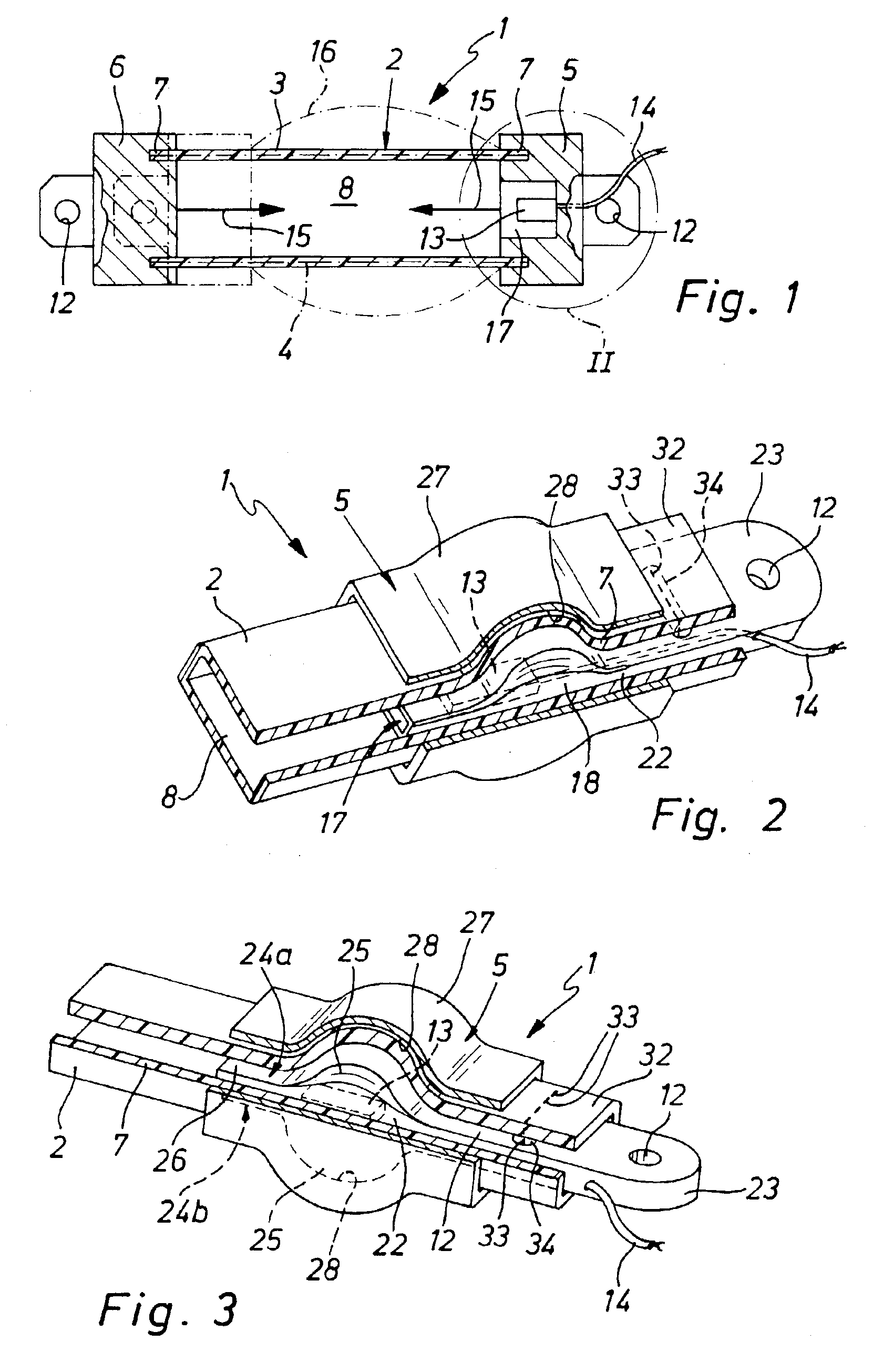
It is in this manner that the pressure medium source for the drive gas is directly associated with the contraction drive. Its design as a pyrotechnic gas generator entails small dimensions and accordingly an optimum integration or adaptation on the contraction drive. The ducts carrying the drive gas produced to the working space may be extremely short and designed with a large cross section, there even being the possibility of locating the gas generator directly in the working space of the contraction drive so that the production of the drive gas takes place directly at the position where the drive gas is required for generating pressure. Since there is no need to lay fluid pipes leading to the contraction drive, installation is moreover quite simple, even in the case of limited space or in the case of lack of accessibility of the spaces. If the pyrotechnic gas generator is designed for electrical ignition, only relatively simple wiring will be required or it is even possible to have a wireless transmission of the ignition signals.
It is an advantage for the contraction drive to possess a respective force applying unit arranged at the two end portions of the contractible hose to render possible the use of the drive force produced, the gas generator being secured in one of the force applying units. It is more particularly possible for at least one force applying unit to comprise a receiving recess open toward the interior space of the contractible hose, in which space the gas generator is placed. Given a suitable design of the receiving recess the latter may ensure a shielding of the contractible hose from the effects of firing of the gas generator so that damage to the contractible hose is prevented.
If there is an additional provision for the force applying part and the retaining cuff to be able to be moved to limited extent in the draw direction of the contractible hose toward each other, a self-limiting effect may occur when contraction forces exist, such effect causing the contractible hose, which is subject to a pulling force, is braced between the retaining cuff and the force applying part in addition.
In order to strengthen the force transmitting join between the contractible hose and the force applying part these two components may be additionally sewn together. If the contractible hose extends past the retaining cuff at its free end and at this free end is secured by sewing to the force applying part, splaying outward of this seam may be restricted owing to the positive engagement and accordingly it may be secured. Furthermore, the thermal load on the stitches is minimized.

Problems solved by technology

This is normally owing to the insufficient cross section and / or the excessive length of the lines conducting the drive gas from the pressure source to the contraction drive.

Method used


Image

  • Gas operated contraction drive
  • Gas operated contraction drive

Examples


Embodiment Construction

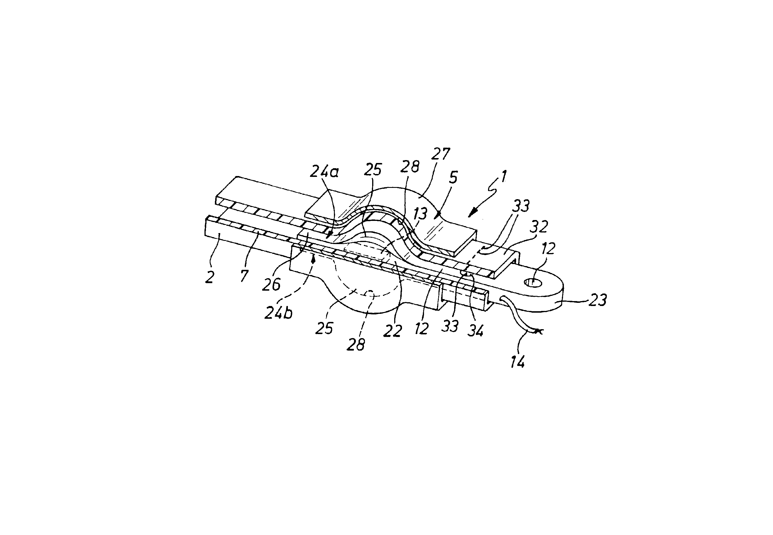
A gas operated contraction drive generally referenced 1 is illustrated in the drawing, which is suitable for any desired application, in the case of which at least two bodies or structures are to be moved in relation to one another.

The contraction drive 1 has a structure with a linear extent and configured in a hose-like form, which is termed a contractible hose 2. In the working embodiment illustrated the contractible hose 2 comprises a hose body 3 consisting of a rubber-like material and a tensile fiber arrangement 4 which is coaxial to the hose body 3 and is preferably at least partially embedded in the wall of the hose body 3. The arrangement 4 is only diagrammatically indicated in the drawings.

The contractible hose 2 extends between two force applying units 5 and 6, which may be termed head pieces. The two end sections 7 of the contractible hose are attached to the respectively associated force applying unit 5 and 6 for the transmission of draw forces.

A working space 8 is joint...


PUM


Abstract

A gas operated contraction drive with a contractible hose, which undergoes longitudinal contraction when a working space defined by it is subjected to a pressurizing drive gas. The contractible hose is fitted with at least one pyrotechnic gas generator.

Description

BACKGROUND OF THE INVENTIONThe invention relates to a gas operated contraction drive comprising a contractible hose which under the action of pressure of a drive gas in a working space, delimited by the hose, is longitudinally contracted.THE PRIOR ARTA contractible hose of this type is for example described in the patent publication WO 00 / 61952 A1 and the European patent publication 0161750 B1. In this case it comprises a hose body with rubber-elastic properties and a contractible hose made up of a tensile fiber arrangement arranged coaxially in relation to the hose body and attached at the end in a sealing manner to two force applying units. Each force applying part includes suitable force applying means, as for example in the form of threaded holes or attachment eyes, by way of which external application of force may take place. The working space delimited jointly by the contractible hose and the two force applying units may be subjected to the action of a drive gas through one of...

Claims


Application Information

Patent Timeline
Patent Type & Authority Patents(United States)
IPC IPC(8): F15B15/00F15B15/10F15B15/19
CPCF15B15/103F15B15/19Y10T403/21
Inventor SCHWARZ, STEFANLORENZ, BERNDBIRK, KARL
Owner FESTO AG & CO KG
Learn More