Ejector cycle

a technology which is applied in the direction of machine operation mode, refrigeration components, light and heating apparatus, etc., can solve the problems that the efficiency of ejector cycle and nozzle efficiency cannot be improved in a wide load variation area, and the difficulty of minute liquid drops of refrigerant, etc., to achieve the effect of wide load variation area, and improving ejector efficiency and nozzle efficiency

Inactive Publication Date: 2005-03-29
DENSO CORP
View PDF8 Cites 11 Cited by
  • Summary
  • Abstract
  • Description
  • Claims
  • Application Information

AI Technical Summary

Benefits of technology

In view of the foregoing problems, it is an object of the present invention to provide an ejector cycle having an ejector, which effectively improves an ejector efficiency and a nozzle efficiency in a wide load variation area of the ejector cycle.
According to an ejector cycle of the present invention, an ejector includes a nozzle for decompressing and expanding refrigerant flowing from a high-pressure heat exchanger by converting pressure energy of refrigerant to speed energy of the refrigerant, and a pressure-increasing portion that is disposed to increase a pressure of refrigerant by converting the speed energy of refrigerant to the pressure energy of refrigerant while mixing refrigerant injected from the nozzle and refrigerant sucked from a low-pressure heat exchanger. Further, a gas-liquid separator for separating refrigerant from the ejector into gas refrigerant and liquid refrigerant, includes a gas refrigerant outlet coupled to a refrigerant suction side of a compressor, and a liquid refrigerant outlet coupled to a refrigerant inlet side of the low-pressure heat exchanger. In the ejector cycle, a variable throttle is disposed in a refrigerant passage between a high-pressure heat exchanger and the ejector, and the variable throttle has a throttle opening degree that is variable such that a refrigerant super-heating degree at a refrigerant outlet side of the low-pressure heat exchanger or at a refrigerant suction side of the compressor becomes in a predetermined range. Therefore, it is possible to suitably decompress refrigerant before being introduced into the nozzle of the ejector. Accordingly, ejector efficiency and nozzle efficiency can be effectively improved while a sufficient cooling capacity can be obtained in the ejector cycle, in a wide load vibration area of the ejector cycle.
Preferably, the variable throttle is disposed to decompress high-pressure refrigerant from the high-pressure heat exchanger, to a gas-liquid two-phase state. Therefore, the nozzle efficiency and the ejector efficiency can be effectively improved in the wide load vibration area of the ejector cycle.
For example, the variable throttle is a mechanical expansion valve that mechanically operates based on the refrigerant super-heating degree sensed by a sensing portion. Alternatively, the variable throttle is an electrical throttle that is electrically operated based on the refrigerant super-heating degree detected by a sensor. Accordingly, the throttle opening degree of the variable throttle can be accurately controlled based on the super-heating degree.
Preferably, at least a part of the variable throttle is integrated with the ejector. In this case, the structure of the ejector cycle can be made simple, and the size of the ejector cycle can be reduced.

Problems solved by technology

On the other hand, in a center portion separated from the inner wall surface, because refrigerant is difficult to boil, liquid drops of refrigerant are difficult to become minute.
Therefore, the nozzle efficiency and the ejector efficiency of the ejector cycle cannot be improved in a wide load variation area.

Method used


Image

  • Ejector cycle
  • Ejector cycle
  • Ejector cycle

Examples


first embodiment

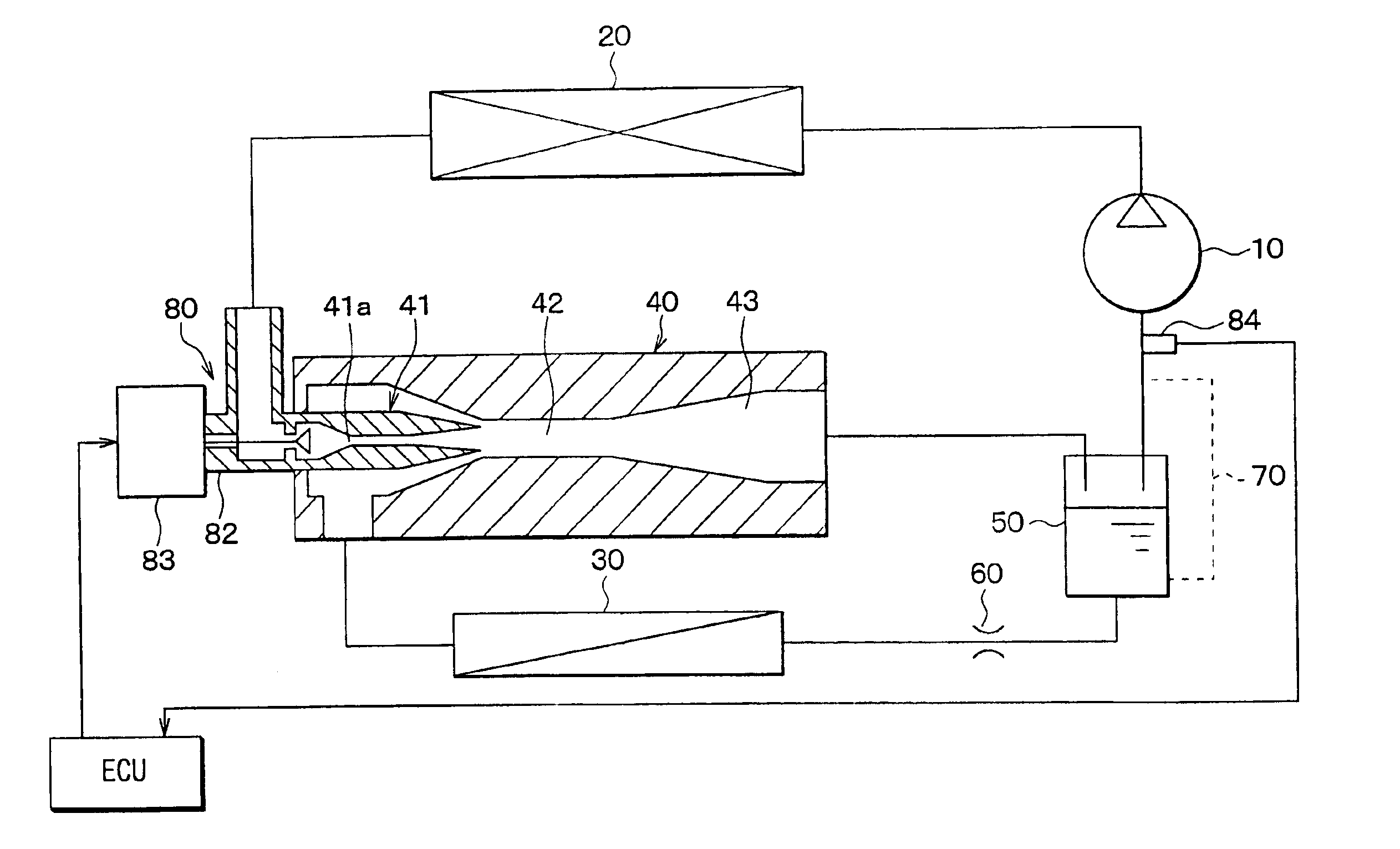
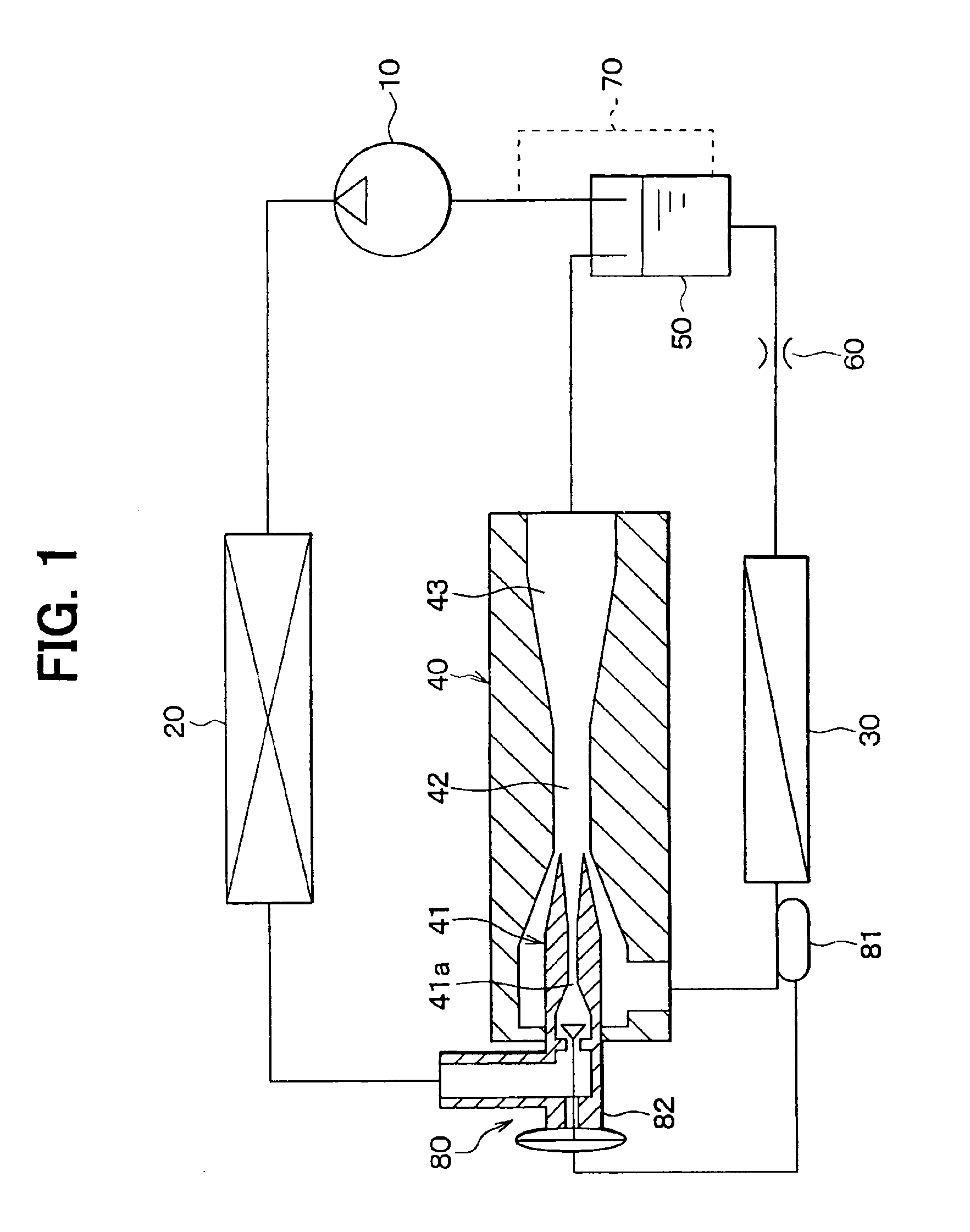
In the first embodiment, an ejector cycle is typically used for a vapor compression refrigerator used for a showcase for refrigerating foods. As shown in FIG. 1, a compressor 10 is an electric compressor for sucking and compressing refrigerant circulated in the ejector cycle. A radiator 20 is a high-pressure heat exchanger for cooling high-temperature and high-pressure refrigerant discharged from the compressor 10 by performing heat-exchange operation between outside air and the high-temperature and high-pressure refrigerant. Further, an evaporator 30 is a low-pressure heat exchanger for cooling air to be blown into the showcase by evaporating liquid refrigerant, more specifically, by performing heat-exchange operation between the air and low-pressure refrigerant. An ejector 40 sucks refrigerant evaporated in the evaporator 30 while decompressing and expanding refrigerant flowing out from the radiator 20 in a nozzle 41, and increases pressure of refrigerant to be sucked into the com...

second embodiment

In the above-described first embodiment, the throttle opening degree of the variable throttle 80 is controlled so that the super-heating degree of the refrigerant at the outlet side of the evaporator 30 becomes in the predetermined range. However, in the second embodiment, the throttle opening degree of the variable throttle 80 is controlled so that the super-heating degree of the refrigerant at a refrigerant suction side of the compressor 10 becomes in a predetermined range (e.g., 0.1-30 degrees). That is, the temperature sensing portion 81 is disposed at the refrigerant suction side of the compressor 10, and the throttle opening degree of the variable throttle 81 is controlled so that the super-heating degree at the refrigerant suction side of the compressor 10 becomes in the predetermined range.

In the second embodiment, the other parts are similar to those of the above-described first embodiment, and detail description thereof is omitted. Therefore, the advantages described in th...

third embodiment

In the above-described first and second embodiments, the variable throttle 80 is a mechanical variable throttle in which its throttle opening degree is mechanically changed based on the pressure difference and the like. However, in the third embodiment, as shown in FIGS. 4 and 5, an electrical temperature sensor 84 is disposed to detect a refrigerant temperature, and an actuator 83 is controlled by an electronic control unit (ECU) based on the signal from the electrical temperature sensor 84, so that the throttle opening degree of the variable throttle 80 is controlled. In the example of FIG. 4, the electrical temperature sensor 84 is disposed at the refrigerant outlet side of the evaporator 30 to detect the refrigerant temperature (refrigerant super-heating degree) at the refrigerant outlet side of the evaporator 30. Therefore, in this case, the ECU controls the actuator 63 to control the throttle opening degree of the variable throttle 80, so that the super-heating degree at the r...


PUM


Abstract

In an ejector cycle with an ejector including a nozzle for decompressing refrigerant, a variable throttle is disposed upstream from the nozzle of the ejector to decompress and expand high-pressure refrigerant flowing from a radiator. For example, the variable throttle decompresses and expands the high-pressure refrigerant in a gas-liquid two-phase state at an upstream position from the nozzle of the ejector. The variable throttle controls a throttle opening degree so that a refrigerant super-heating degree at a refrigerant outlet side of an evaporator or at a refrigerant suction side of a compressor becomes in a predetermined range. Accordingly, the ejector cycle has an improved nozzle efficiency and an improved ejector efficiency in a wide load variation range of the ejector cycle.

Description

CROSS-REFERENCE TO RELATED APPLICATIONThis application is related to and claims priority from Japanese Patent Application No. 2002-202724 filed on Jul. 11, 2002, the contents of which are hereby incorporated by reference.BACKGROUND OF THE INVENTION1. Field of the InventionThe present invention relates to an ejector cycle including an ejector. In the ejector cycle, a variable throttle is disposed upstream from a nozzle of the ejector, so that high-pressure refrigerant is decompressed in the variable throttle, before being decompressed in the nozzle.2. Description of Related ArtIn an ejector cycle, refrigerant is decompressed and expanded in a nozzle of an ejector so that gas refrigerant evaporated in an evaporator is sucked, and pressure of refrigerant to be sucked into a compressor is increased by converting expansion energy to pressure energy. In the nozzle of the ejector, the pressure energy of the refrigerant is converted to the speed energy thereof. Further, because refrigerant ...

Claims


Application Information

Patent Timeline
Patent Type & Authority Patents(United States)
IPC IPC(8): F25B41/00F25B9/00F25B41/06F25B1/00
CPCF25B41/00F25B9/008F25B41/062F25B2309/061F25B2700/21175F25B2341/0013F25B2500/01F25B2500/18F25B2700/21151F25B2341/0012F25B41/34Y02B30/70
Inventor TAKEUCHI, HIROTSUGUNISHIJIMA, HARUYUKIMIZUNO, SYUICHI
Owner DENSO CORP
Why Eureka
Try Eureka