Motor-driven compressor

Inactive Publication Date: 2005-03-29
SANDEN CORP
View PDF3 Cites 11 Cited by
  • Summary
  • Abstract
  • Description
  • Claims
  • Application Information

AI Technical Summary

Benefits of technology

An object of the present invention is to provide a motor-driven compressor which is capable of preventing a suction refrigerant from being

Problems solved by technology

As a result, the rotation efficiency of the electric motor lowers, making the air conditioning system unable to provide the required cooling power.
However, after the refrigerant is used for cooling, the temperature thereof is high since the refrigerant has absorbed the heat of the electric motor and compression unit.
If such high-temperature refrigerant is returned to the suction chamber, the temperature of the suction refrigerant to be compressed by the compression unit undesirably increas

Method used


Image

  • Motor-driven compressor
  • Motor-driven compressor
  • Motor-driven compressor

Examples


first embodiment

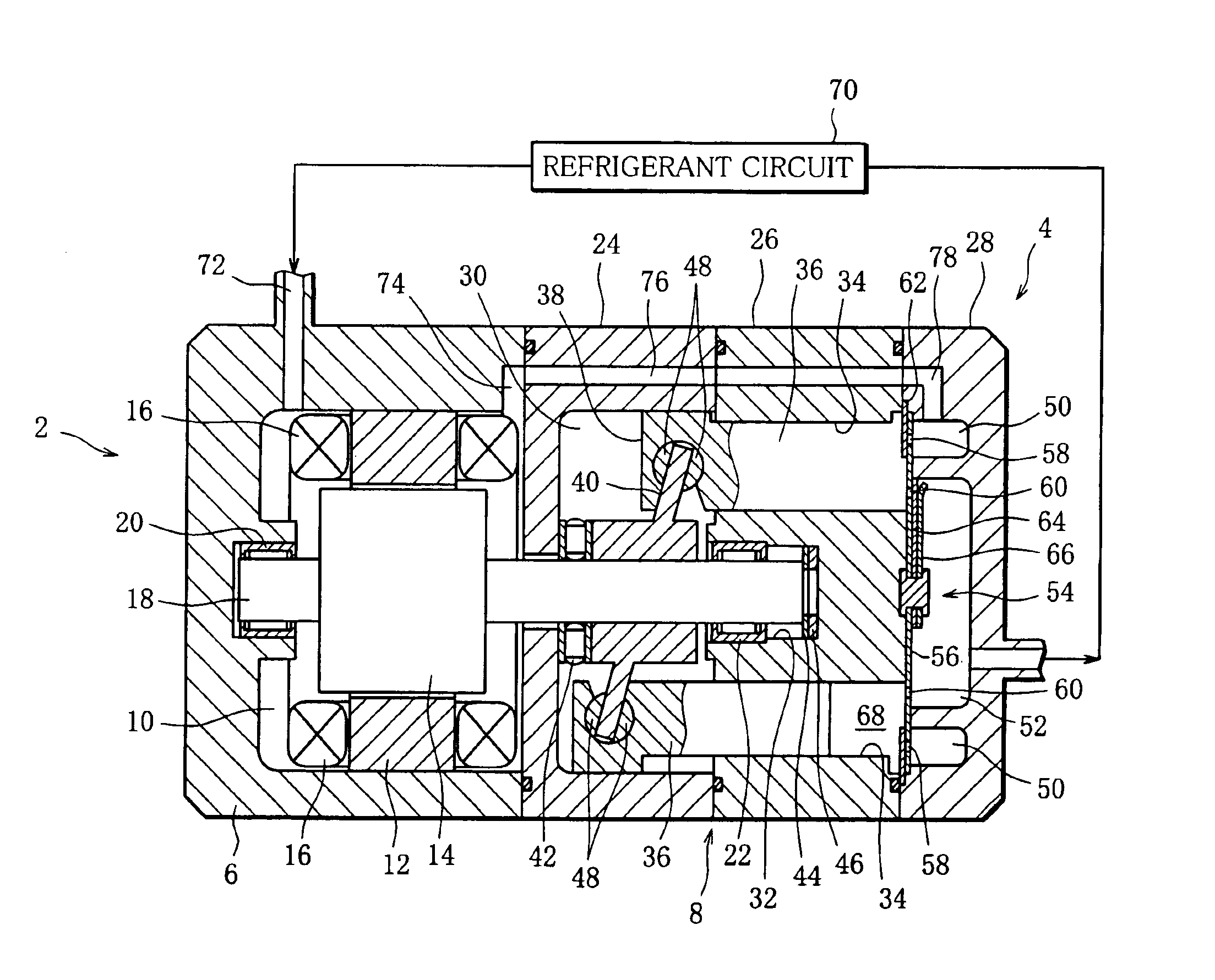
A motor-driven compressor shown in FIG. 1, is incorporated in an air conditioning system of a motor vehicle and is used to compress a refrigerant in the air conditioning system. The motor-driven compressor generally comprises an electric motor 2 and a compression unit 4, and the compression unit 4 has a swash plate-type compression mechanism.

The electric motor 2 has a motor housing 6, in which an armature chamber 10 is defined in cooperation with a unit housing 8 of the compression unit 4. More specifically, the motor housing 6 and the unit housing 8 are coupled together in close contact with each other, and the motor housing 6 is in the form of a hollow cylinder closed at one end and opening at the other and facing the unit housing 8.

The armature chamber 10 accommodates a stator 12, a rotor 14 and numerous coils 16, and the rotor 14 is mounted to a motor shaft 18. The motor shaft 18 is rotatably supported at one end by an end wall of the motor housing 6 through a radial bearing 20...
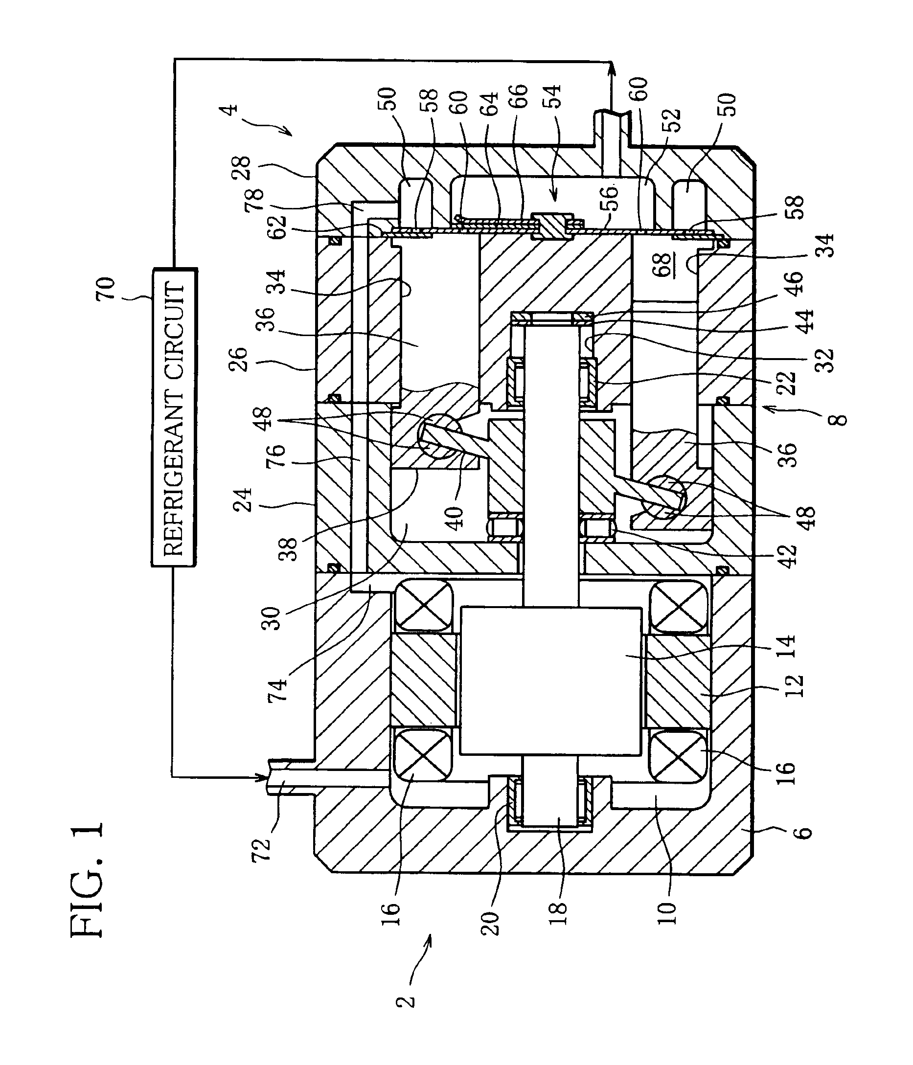
second embodiment

The cooling channel of the second embodiment, shown in FIG. 2, includes a refrigerant pipe 80, in place of the radial groove 74 and the axial passage 76. The refrigerant pipe 80 extends through the crank casing 24 and the cylinder block 26 from the one end face of the crank casing 24 to the other end face of the cylinder block 26. One end of the refrigerant pipe 80 opens into the armature chamber 10, and the other end of same is connected to an outlet 82, in place of the L-shaped passage 78. The outlet 82 is formed through the valve plate 56 to connect the refrigerant pipe 80 and the suction chamber 50 to each other. As clearly shown in FIG. 2, a through hole 84 for passing the refrigerant pipe 80 therethrough is formed in the cylinder block 26 and is located between the cylinder bores 34 as viewed in the circumferential direction of the cylinder block 26.

In the second embodiment, the refrigerant returned from the refrigerant circuit 70 flows into the suction chamber 50 through the ...
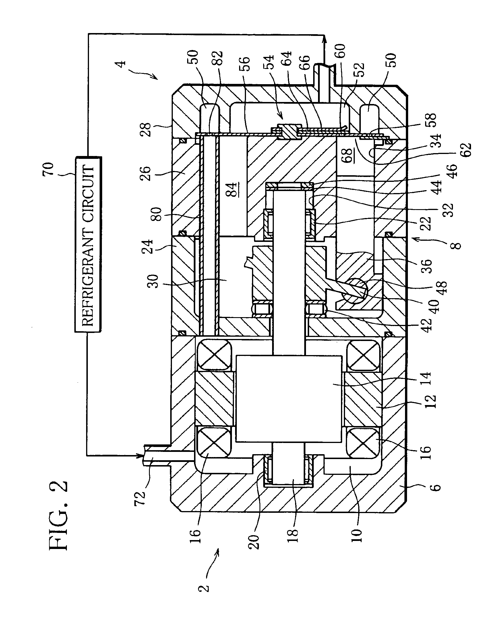
third embodiment

In the third embodiment, the refrigerant returned from the refrigerant circuit 70 flows into the suction chamber 50 through the inlet port 72, armature chamber 10, internal passage 86, holes in the bearing 44 and belleville spring 46, internal passage 88 and outlet 82.

The cooling channel of the fourth embodiment, shown in FIG. 4, has an upstream section including the inlet port 72 and the armature chamber 10, and a downstream section extending from the armature chamber 10 to the suction chamber 50. Unlike the first to third embodiments, the downstream section of the cooling channel is formed outside of the unit housing 8.

More specifically, the downstream section of the cooling channel has an outlet port 90 formed in the outer peripheral wall of the motor housing 6. The outlet port 90 is located near the one end wall of the crank casing 24 and connects the armature chamber 10 and an external pipe 92 to each other. The external pipe 92 extends outside of the unit housing 8 and is conn...


PUM


Abstract

A motor-driven compressor for compressing a refrigerant in an air conditioning system includes an electric motor, a swash plate-type compression unit driven by the electric motor, and a cooling channel for returning the refrigerant used by the air conditioning system to a suction chamber of the compression unit. The cooling channel has an upstream section including an armature chamber of the electric motor, and a downstream section extending from the armature chamber to the suction chamber in such a manner that the downstream section is separated from a crank chamber of the compression unit.

Description

This nonprovisional application claims priority under 35 U.S.C. 119(a) on Patent Application No. 2002-354054 filed in Japan on Dec. 5, 2002, the entire contents of which are incorporated herein by reference.BACKGROUND OF THE INVENTION1. Field of the InventionThe present invention relates to a motor-driven compressor incorporated in an automotive air conditioning system.2. Description of the Related ArtAn air conditioning system for a motor vehicle includes a compressor for compressing a refrigerant and discharging the resultant high-pressure refrigerant. The high-pressure refrigerant is used to cool the interior of the vehicle compartment of the motor vehicle. More specifically, the high-pressure refrigerant is liquefied by a condenser and then evaporated in an evaporator to cool the air which is introduced into the vehicle compartment.As such compressor, a motor-driven compressor directly coupled with an electric motor is known. The motor-driven compressor includes an electric moto...

Claims


Application Information

Patent Timeline
IPC IPC(8): F04B39/06F04B27/08F04B27/10F25B31/00F04B39/12
CPCF04B27/0895F04B39/066F04B27/1036F25B31/006
Inventor TSUNODA, MASATAKA
Owner SANDEN CORP
Why Eureka
Try Eureka