
Back light module

a back light module and module technology, applied in the field of back light modules, can solve the problems of reducing the product life of components related to the back light module, and achieve the effects of preventing malfunctions caused by abnormal temperature of the light source generator, increasing the heat transfer rate of the back light module, and reducing the product life of the components

Inactive Publication Date: 2005-03-29
INNOLUX CORP
View PDF3 Cites 49 Cited by
  • Summary
  • Abstract
  • Description
  • Claims
  • Application Information

AI Technical Summary

Benefits of technology

It is an advantage of the present invention against the prior art that a surface of the reflecting sheet of the back light module comprises the opening and a plurality of vent holes, and the reflecting sheet comprises at least one arc-shaped structure to increase both the reflecting rate and the heat-dissipation area of the reflecting sheet. The heat generated during the operation of the backlight module can be dissipated to the air outside the back light module, and the heat transfer rate of the back light module is therefore improved significantly. Consequently, malfunctions caused by an abnormal temperature of the light source generator are prevented, and product lives of either the back light module or other relative components are increased as well.
against the prior art that a surface of the reflecting sheet of the back light module comprises the opening and a plurality of vent holes, and the reflecting sheet comprises at least one arc-shaped structure to increase both the reflecting rate and the heat-dissipation area of the reflecting sheet. The heat generated during the operation of the backlight module can be dissipated to the air outside the back light module, and the heat transfer rate of the back light module is therefore improved significantly. Consequently, malfunctions caused by an abnormal temperature of the light source generator are prevented, and product lives of either the back light module or other relative components are increased as well.
These and other objectives of the present invention will no doubt become obvious to those of ordinary skill in the art after reading the following detailed description of the preferred embodiment, which is illustrated in the multiple figures and drawings.

Problems solved by technology

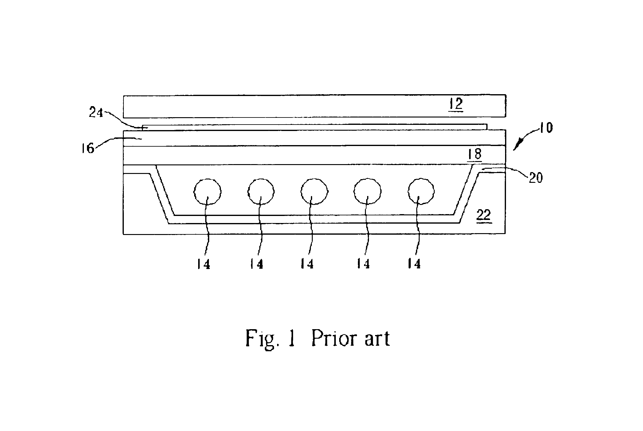
As a result, the heat generated during the operation of the back light module 10 can be entirely dissipated to the air outside the back light module 10 and is therefore accumulated inside the back light module 10, leading to an abnormal high temperature of the light source generator 14, which eventually causes malfunctions and reduces the product lives of components related to the back light module 10.

Method used


Image

  • Back light module
  • Back light module
  • Back light module

Examples


first embodiment

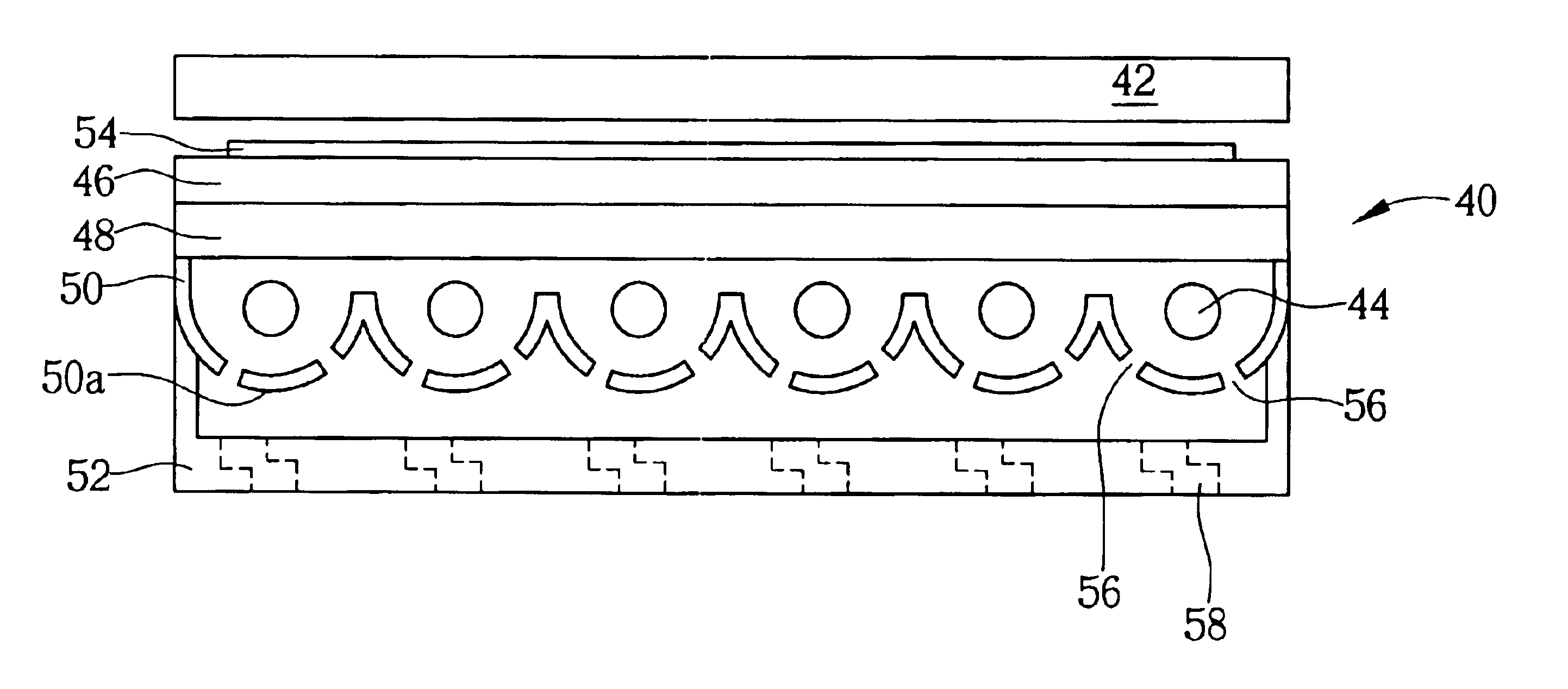
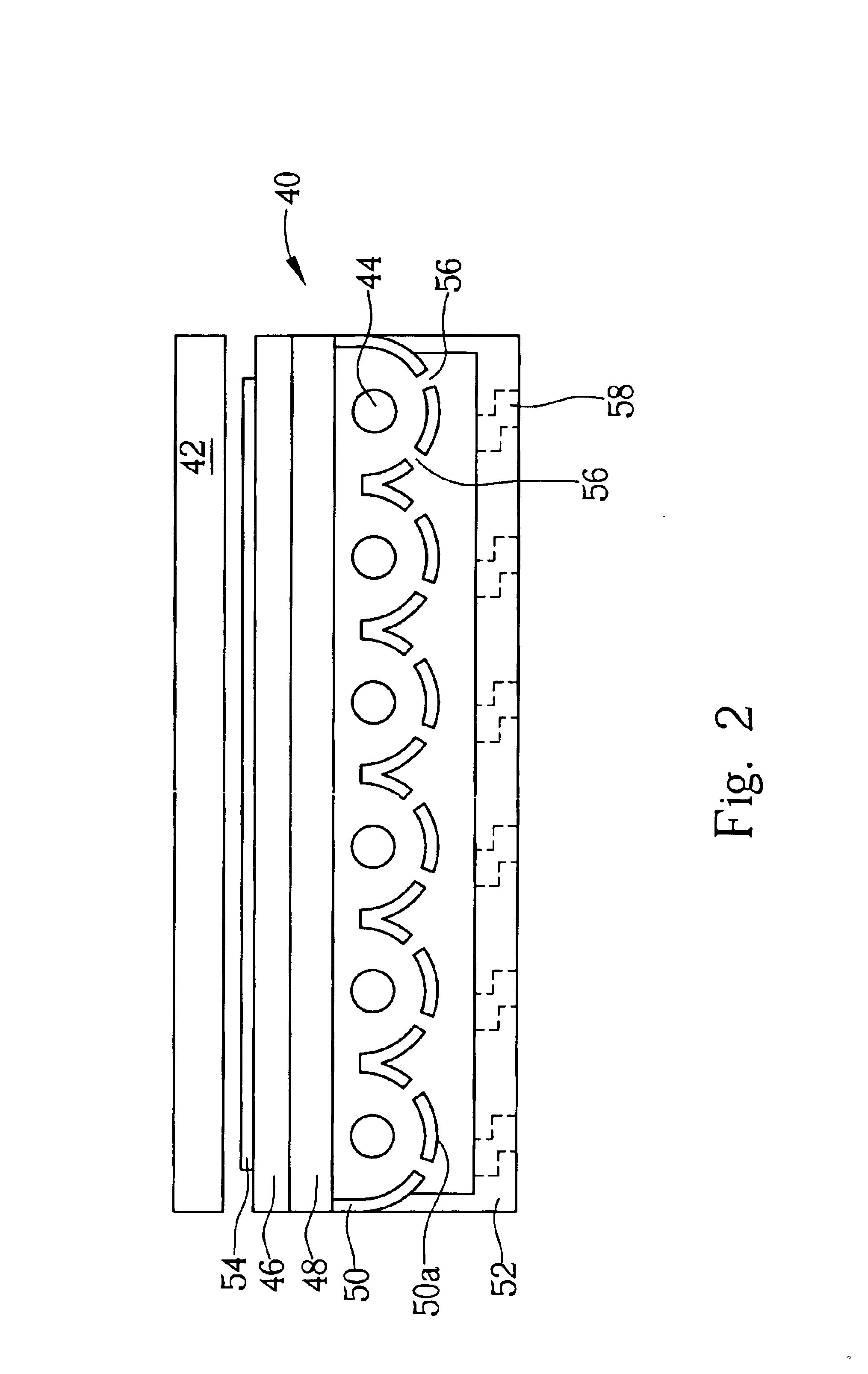
Please refer to FIG. 2 of a cross-sectional view of a back light module 40 according to the present invention. As shown in FIG. 2, the back light module 40 is disposed under a display panel 42 and comprises at least one light source generator 44, a diffusing plate 46 disposed between the light source generator 44 and the display panel 42, a light guide plate (LGP) 48 disposed between the light source generator 44 and the diffusing plate 46, a reflecting sheet 50 disposed under the light source generator 44, and a housing 52 that surrounds the reflecting sheet 50 and comprises a plurality of first vent holes 58.

Normally, the light source generator 44 is a lamp for generating a light source. In the preferred embodiment of the present invention, the light source generator 44 is a cold cathode fluorescent lamp (CCFL), and the cold cathode fluorescent lamps are arranged in parallel. The reflecting sheet 50 is composed of either aluminum (Al) or an alloy, and is employed to reflect the li...

second embodiment

Please refer to FIG. 6 of an enlarged schematic view of the column 81. As shown in FIG. 6, the column 81 comprises a first end 81a and a second end 81b respectively contacted with the light source generator 74 and the reflecting sheet 80. The first end 81a comprises a rubber pad 90, and the second end 81b comprises a metal surface 92. In the preferred embodiment of the present invention, the metal surface 92 is a silver-plated surface with an excellent heat conductibility, and the rubber pad is employed not only to transfer the heat generated by the light source generator 74 during the operation of the back light module 70, but also to prevent the light source generator 74 from damage caused by vibration during transportation. Therefore, in the present invention, the heat generated by the light source generator 74 during the operation of the back light module 70 is dissipated to a space under the reflecting sheet 80 conductively via the column 81 and the second vent hole, and is the...


PUM


Abstract

A back light module disposed under a display panel has at least a light source generator for generating light beams, a diffusing plate for scattering the light beams to the display panel, a light guide plate (LGP) for scattering the light beams to the diffusing plate, a reflecting sheet for scattering the light beams to the light guide plate. The reflecting sheet has at least an opening for dissipating heat generated by the operation of the light source generator of the back light module.

Description

BACKGROUND OF THE INVENTION1. Field of the InventionThe present invention relates to back light module, and more specifically, to a back light module with an improved heat transfer rate.2. Description of the Prior ArtBacklight units are known in the art. The backlight unit, which is a key element in the fabrication of liquid crystal displays, is widely used in digital cameras, PDAs, vehicle satellite navigation systems, computer monitors, flat panel TVs and so on. Typically, a backlight unit, which is generally installed underneath a display panel, comprises a light source (or multiple light sources) and a light diffusion means for providing users and consumers with diffused, ample, and comfortable backlighting. Light penetrates the overlying display panel and forms various images controlled by pixel electrodes densely arranged on the display panel. Backlight units are typically divided into two major categories: edge light type and direct-type, wherein the direct-type backlight uni...

Claims


Application Information

Patent Timeline
IPC IPC(8): F21V29/00G02F1/1335G02F1/13G02F1/13357
CPCF21S48/328F21V29/004G02F1/133605F21V29/83G02F2201/36G02F2201/503G02F2001/133628G02F1/133628
Inventor MAI, CHE-KUEI
Owner INNOLUX CORP
Learn More