Quick install blade arms for ceiling fans

a technology for ceiling fans and blade arms, which is applied in the direction of waterborne vessels, machines/engines, fastening devices, etc., can solve the problems of user injury, user loss of balance, and increased installation time and cost, and achieves the effect of easy and quick installation

Inactive Publication Date: 2005-03-29
CHIEN LUEN INDS
View PDF41 Cites 45 Cited by
  • Summary
  • Abstract
  • Description
  • Claims
  • Application Information

AI Technical Summary

Benefits of technology

The first objective of the present invention is to provide detachable blade arms for ceiling fans that are easy and quick to install.

Problems solved by technology

Many problems occur from this traditional method of having one person installing a ceiling fan.
Screws 50 can and do accidentally fall and become lost causing more time and more expense to finish the installation.
The blade 30 and mounting arm 40 have been known to fall on and cause injury to the user 60 during assembly.
Additionally, the user can lose their balance and injure themselves as well as falling off the ladder and stool.
Additional problems also occur after installation.
For example, uneven tightening of each of the plural fasteners that connect the mounting arm to the motor has resulted in wobble effects when the ceiling fan system is running.
Thus, the current operation of assembly has become known as a frustrating, undesirable, difficult, tedious, time consuming and sometimes dangerous task.
To merely add a second worker to help in the assembly installation may solve some of the problems above, but would add additional cost and labor expense to the installation project.
In addition to the difficulty of having to screw the blade arms onto the ceiling fan motor endshield, the endshield contains unsightly screw heads that detract from the appearance of the ceiling fan itself.
Another problem with using screw type fasteners is that the fasteners themselves can loosen causing the blade arms and connected blades to accidentally fall resulting in damages to surrounding property and people beneath the ceiling fans.
Existing fan blades and blade arms are hard to remove from the ceiling mounted motors.
This messy cleaning with brushes causes the dirt to fall on both the cleaner and furniture and flooring beneath the fan.

Method used


Image

  • Quick install blade arms for ceiling fans
  • Quick install blade arms for ceiling fans
  • Quick install blade arms for ceiling fans

Examples


first embodiment

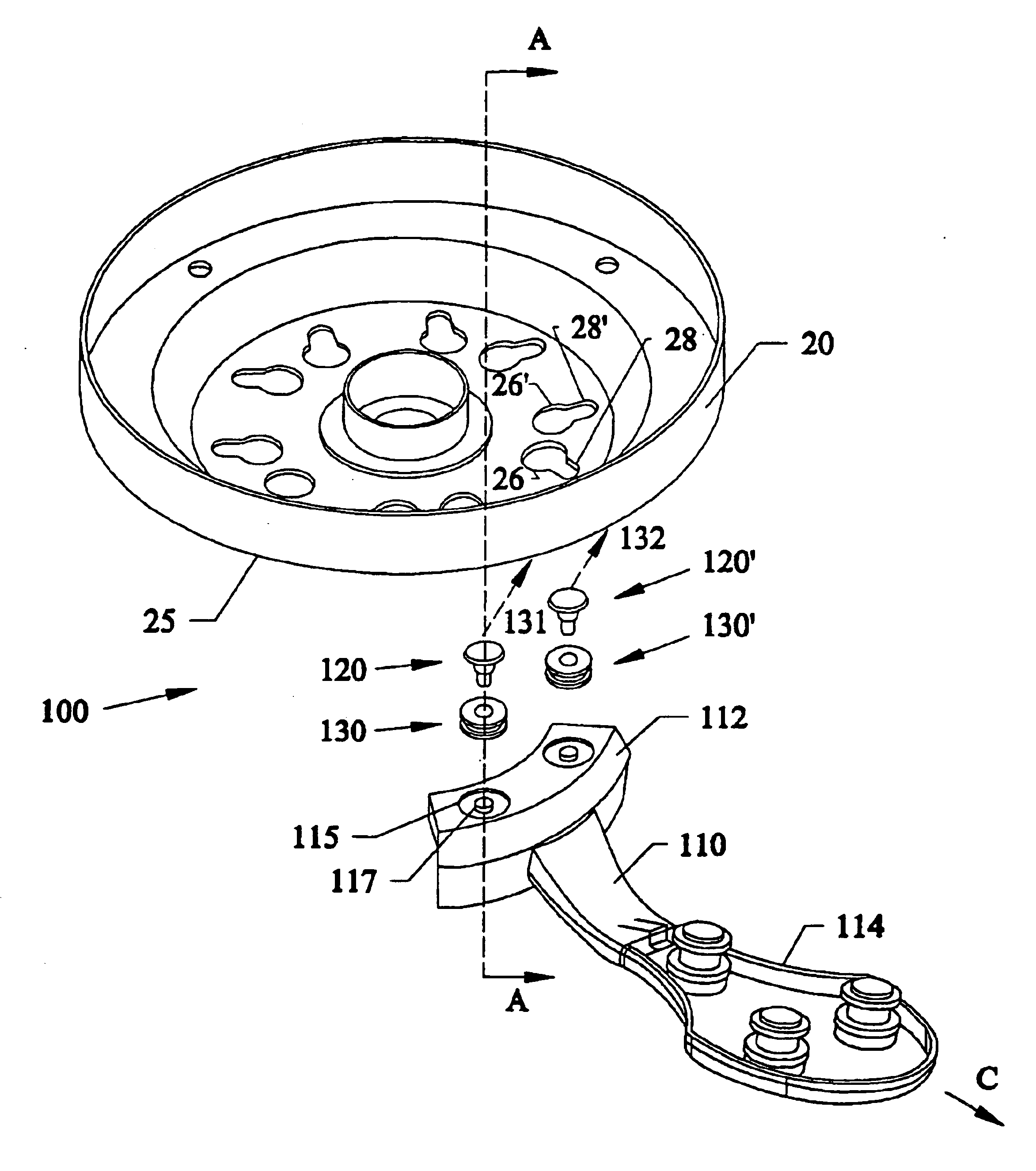
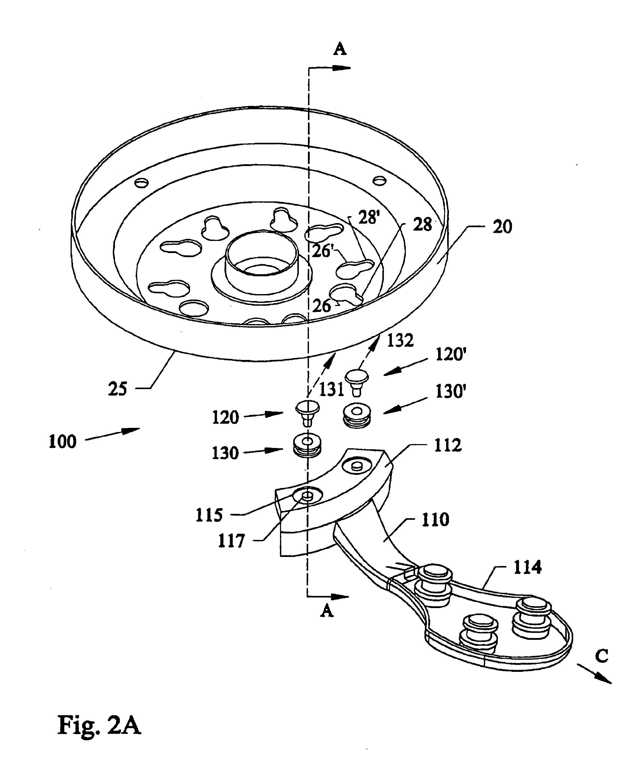
FIG. 2A is a perspective exploded view of a first embodiment 100 of the slip and lock fasteners 120, 120′, grommets 130, 130′, mounting arm 110, and rotor 20, 25 used for the subject invention. FIG. 2B is a side cross-sectional view of an assembled slide and lock fastener 120 and associated components of FIG. 2A along arrow A after being assembled and attached. FIG. 2C is an enlarged view of the slide and lock fastener of FIG. 2B with the protruding member 120 on the blade arm 110 and the slot 115 on the rotor 120, 125. FIG. 2D is a view of the flat-headed fastener screw 120 of FIG. 2C.

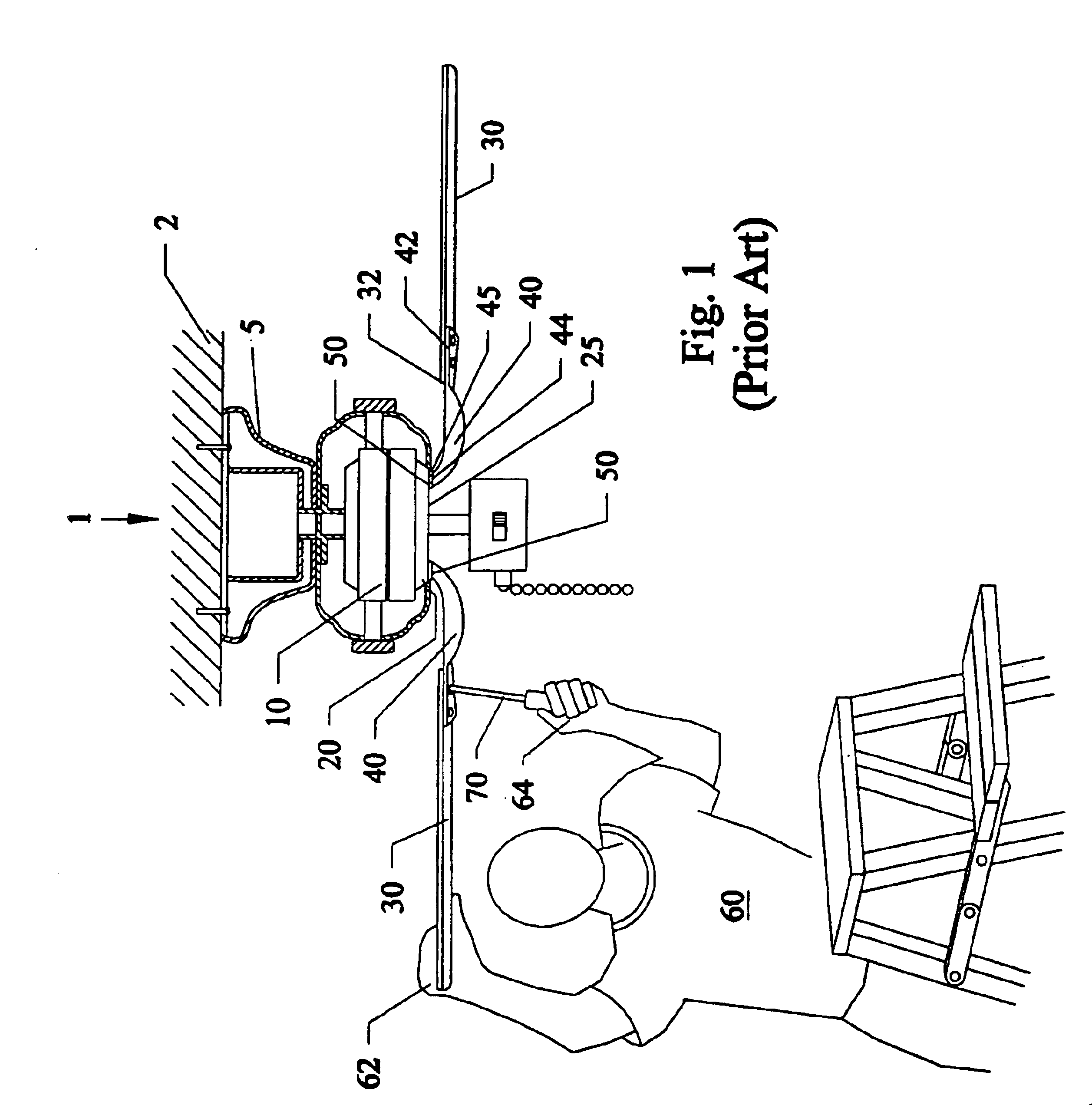
Referring to FIGS. 2A-2C, a mounting arm 110 has one end 114 connected to blade arms(not shown). End 114 can be connected to blade arms similar to that shown in FIG. 1. Alternatively, mounting arm 110 can be connected to detachable slide and lock blade fasteners such as those described in U.S. Ser. No. 09 / 200,607 filed Nov. 30, 1998 now U.S. Pat. No. 6,171,059 and U.S. application Ser. No. 08 / 851,501 ...

second embodiment

FIG. 3A is an exploded view of a second embodiment 200 of a quick install snapable mounting arm 210 for attaching to the rotor 20, 25 of a ceiling fan. FIG. 3B is a side cross-sectional view of the mounting arm 210 and rotor 20, 25 of FIG. 3A being attached together in the direction along arrow D. FIG. 3C is an enlarged view of the inwardly deformable snap fastener 220 and rotor 20, 25 of FIG. 3B. FIG. 3D is an enlarged view of the inwardly deformable snap fastener 220 of FIG. 3C.

Referring to FIGS. 3A-3D, mounting arm 210 can have one end 214 connected to ceiling fan blades similar to that shown in FIG. 1. Alternatively, blade connection end 214 can be attached to detachable slide and lock blade fasteners such as those described in U.S. Ser. No. 09 / 200,607 filed Nov. 30, 1998, now U.S. Pat. No. 6,171,059 and U.S. application Ser. No. 08 / 851,501 filed on May 5, 1997, now U.S. Pat. No. 6,010,306 both by the same assignees as that of the subject invention, which are both incorporated b...

third embodiment

FIG. 4A is an exploded view the third embodiment 300 of a removable quick install snap fastener 320 on the rotor 20, 25 of a ceiling fan that attaches to a mounting arm 310 and deformable gasket 330 therebetween. FIG. 4B is a side cross-sectional view of the mounting arm 310 and rotor 20, 25 of FIG. 4A being attached together along arrow G. FIG. 4C is a side view of the snap fastener of FIG. 4B.

Referring to FIGS. 4A-4C, mounting arm 310 has an end 314 that connects to ceiling fan blades similar to that shown in FIG. 1. Alternatively, blade connection end 314 can be attached to detachable slide and lock blade fasteners such as those described in U.S. Ser. No. 09 / 200,607 filed Nov. 30, 1998, now U.S. Pat. No. 6,171,059 and U.S. application Ser. No. 08 / 851,501 filed on May 5, 1997, now U.S. Pat. No. 6,010,306 both by the same assignees as that of the subject invention, which are both incorporated by reference. End 312 has a centrally located rectangular through-hole slot 315 and two up...


PUM

PropertyMeasurementUnit
centrifugal forceaaaaaaaaaa
timeaaaaaaaaaa

Abstract

Quick attachable and detachable mounting arms for ceiling fans. A first version has flat headed fasteners initially attached to one end of mounting arms, with key-hole slots in the endshield of the ceiling fan motor. The user raises the mounting arm so that the flat headed fasteners fits through the larger openings in the keyhole slots and then pulls the mounting arm outward until the arm locks in place by the smaller opening portions of the keyhole slots. Rubber type gaskets and washers help lock and hold the mounting arms in place. The flat headed fasteners can also be located on the endshields with the keyhole slots on mounting arms. A second embodiment includes inwardly deformable springably snapable fasteners that can be located on the ends of the mounting arms which can deform inwardly and expand after passing through slots on the endshield of the rotor. Alternatively, the fasteners can be located on the bottom of the endshield with the receiving slots on the ends of the mounting arms. The different versions can include guide posts for allowing only one single fastener to be needed. A third embodiment allows the inwardly bendable snapable fasteners to be removable with screws.

Description

BACKGROUND AND PRIOR ARTMost conventional ceiling fans are similarly installed. FIG. 1 shows a partial side view of a conventional ceiling fan unit 1 that encompasses a general prior art ceiling fan system. In FIG. 1, ceiling fan motor 10 has a rotor component 20 that rotates about a central axis beneath motor 10, which is in turn connected to a housing 5 that is attached beneath a ceiling 2. A plurality of fan blades 30 are connected to the rotor 20 by mounting arms 40. Each mounting arm 40 has one end 42 connected to an end 32 of each fan blade 30, and a second end 44 having at least two through-holes 45 therethrough, so that conventional fasteners such as screws 50 pass through the through-holes 45 to mateably thread into threaded holes 25 in the bottom of rotor 20.Usually most conventional directions have the installer first connect and hang the motor 10, rotor 20 and housing 5 to a ceiling. More often than not the installer is usually perched on a stool or ladder. Next, many di...

Claims


Application Information

Patent Timeline
Patent Type & Authority Patents(United States)
IPC IPC(8): F04D25/08F04D25/02F04D29/34F04D29/32F16B5/06F16B21/09
CPCF04D25/088F04D29/34F16B5/0642F16B5/065F16B5/0664Y10T403/606Y10T29/49318Y10T403/60Y10T29/49316Y10T403/5713Y10T29/49327F16B21/09
Inventor BUCHER, CHARLES E.BUCHER, JOHN C.
Owner CHIEN LUEN INDS
Why Eureka
Try Eureka