

Liquid crystal display unit and display control method therefor
- Summary
- Abstract
- Description
- Claims
- Application Information
AI Technical Summary
Benefits of technology
Problems solved by technology
Method used
Image

Examples
first embodiment
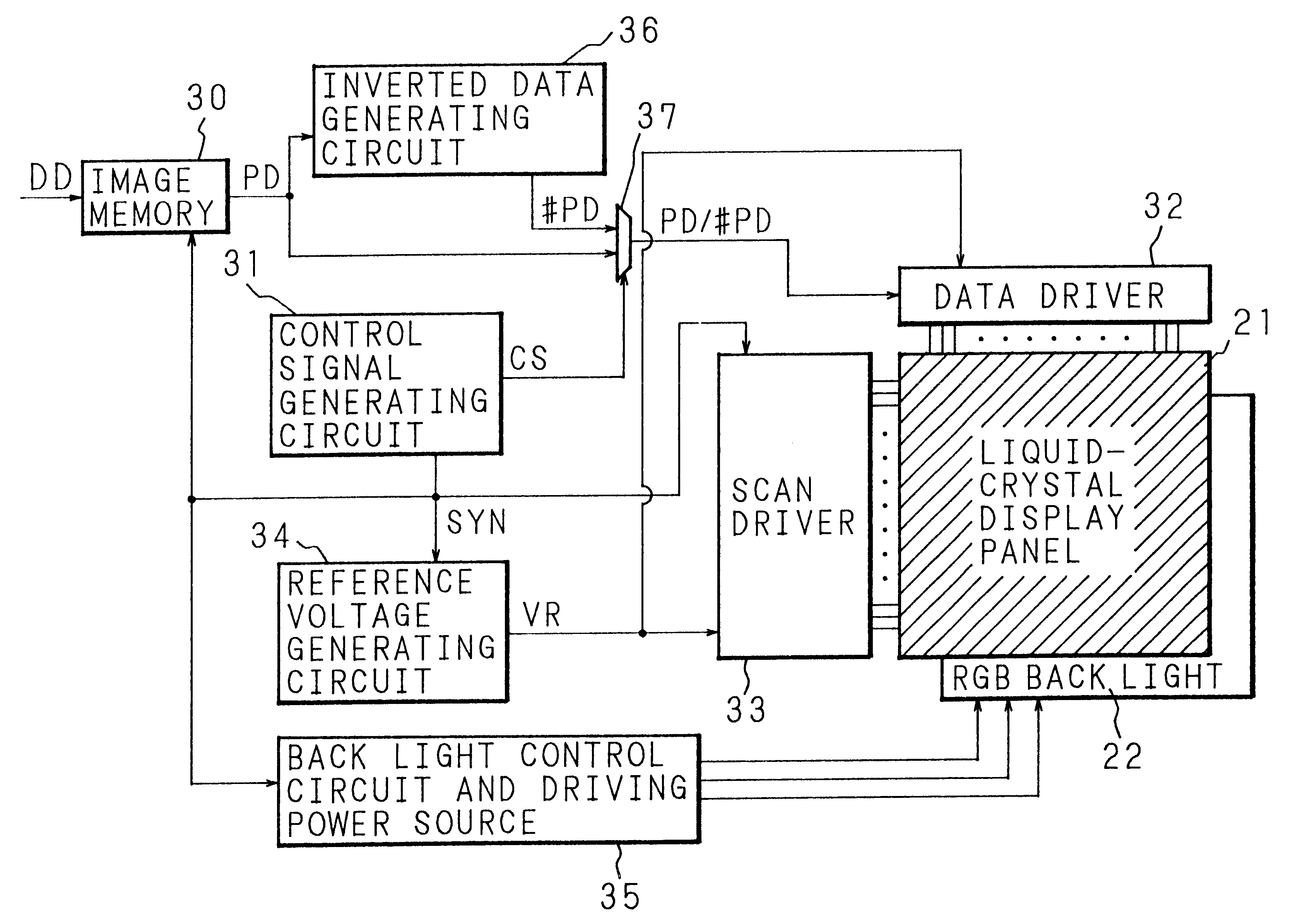
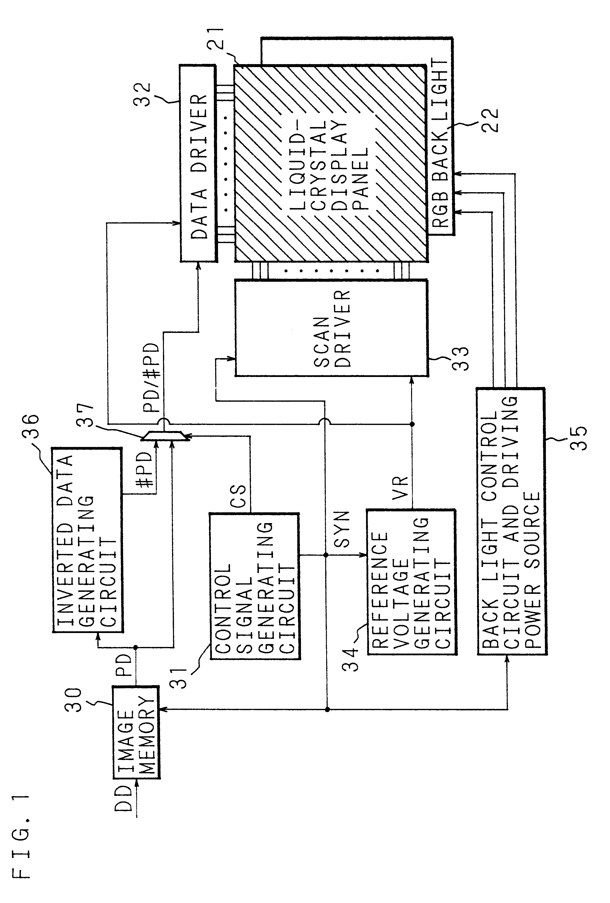
Display operation of the liquid crystal display unit as described above according to the present invention will be described hereinafter. FIG. 5 is a time chart showing a relationship between light emission timing in LEDs of respective colors of the back light 22 and scanning timing of respective lines in the liquid crystal panel 21 and for explaining the principle of a first embodiment in a display control method of the liquid crystal display unit according to the present invention.
As shown in FIG. 5(a), the LEDs of the back light 22 are allowed to be luminous successively in the order of red, green, and blue in, for example, every 5.6 ms, and respective pixels in the liquid crystal panel 21 are switched in synchronous with the light emission with a line unit to display an image. When display in 60 frames for 1 second is carried out, a period for one frame becomes 16.6 ms. The period for the one frame is further divided into 3 sub-frames in every 5.6 ms, and the LEDs of the respect...
second embodiment
Meanwhile, in the above-mentioned time-shared color liquid crystal display, only the half of the amount of light emission of the back light 22, more specifically of the LED array 7 is utilized in the worst case, it is wasteful in view of power consumption. This is an important problem for transportable office automation equipment which is usually driven by battery. In this connection, the second embodiment wherein more reduction of power consumption can be realized in the above-mentioned display control method will be described herein.
The time chart of FIG. 8 shows a relationship between an amount of light emission in the back light 22 and a display condition in the liquid crystal panel 21 in the above-mentioned first embodiment. As shown in FIG. 8(a), it is arranged in such that in a sub-frame period of time of 5.6 ms, the first application of voltage begins at the same time of starting time of the sub-frame, and continues for 2.8 ms of the following period of time, while the secon...
third embodiment
A specific example of the third embodiment as described above will be described hereinafter. Since the liquid crystal panel 21 used herein is substantially the same as that used in the above-mentioned respective examples (except that scanning of TFT is made to be capable of dividing into two blocks, i.e., the upper and the lower sections), the explanation therefor is omitted, and the display control as shown in the time chart of FIG. 13 was applied thereto.
As shown in FIG. 13(b), first, in a red sub-frame, writing scanning of pixel data PD / writing scanning of inverted pixel data #PD are carried out with respect to respective lines in the liquid crystal panel 21. As shown in FIG. 13(a), the back light 22 is allowed to emit light during a period of time from the time at which writing of the pixel data PD with respect to all the lines of the liquid crystal panel 21 was completed to the time at which writing of the inverted pixel data #PD is started. As a result, as shown in FIG. 13(c),...
PUM
 Abstract
Description
Claims
Application Information