Control system for internal combustion engine

a control system and internal combustion engine technology, applied in the direction of electric control, machines/engines, output power, etc., can solve the problem of strange feeling of the driver of the vehicle, and achieve the effect of removing the strange feeling of the vehicle behavior

Inactive Publication Date: 2005-04-05
HONDA MOTOR CO LTD
View PDF5 Cites 6 Cited by
  • Summary
  • Abstract
  • Description
  • Claims
  • Application Information

AI Technical Summary

Benefits of technology

It is accordingly an object of the present invention to provide a control system for an internal combustion engine that can eliminate the strange feeling in the vehicle behavior due to the cleaning operation of the hydraulic control valve for controlling the operation of the valve operating characteristic varying mechanism.
With this configuration, the operation of the intake air amount control means is controlled according to the operating condition of the valve operating characteristic varying mechanism when the cleaning operation for the hydraulic control valve is performed. Accordingly, changes in the intake pressure during the cleaning operation can be suppressed to thereby eliminate a strange feeling in the vehicle behavior. For example, when the valve operating characteristic varying mechanism continuously varies the operating phase of the intake valve with a fixed operating phase of the exhaust valve, the intake air amount control means is controlled so that the intake air amount decreases with an advance in the operating phase of the intake valve, thereby suppressing changes in the intake pressure due to changes in the operating phase of the intake valve. As a result, a strange feeling in the vehicle behavior can be eliminated.
Preferably, the cleaning means gradually increases an amplitude of change in the opening degree of the hydraulic control valve to perform the cleaning operation.

Problems solved by technology

As a result, a feeling of deceleration of the vehicle changes even when the vehicle is decelerated by the engine brake, or when the fuel supply to the engine is interrupted, which often causes a strange feeling to a driver of the vehicle.

Method used


Image

  • Control system for internal combustion engine
  • Control system for internal combustion engine
  • Control system for internal combustion engine

Examples


Embodiment Construction

A preferred embodiment of the present invention will now be described with reference to the drawings.

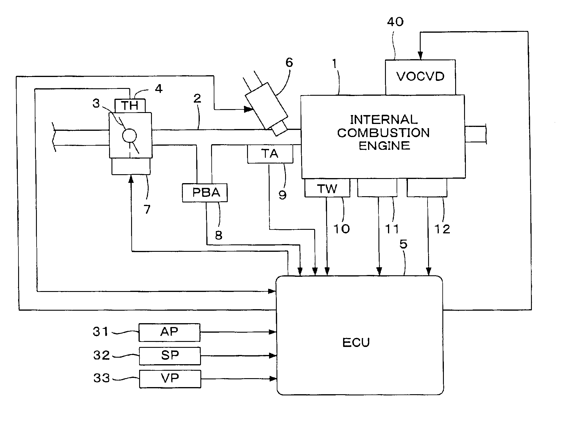
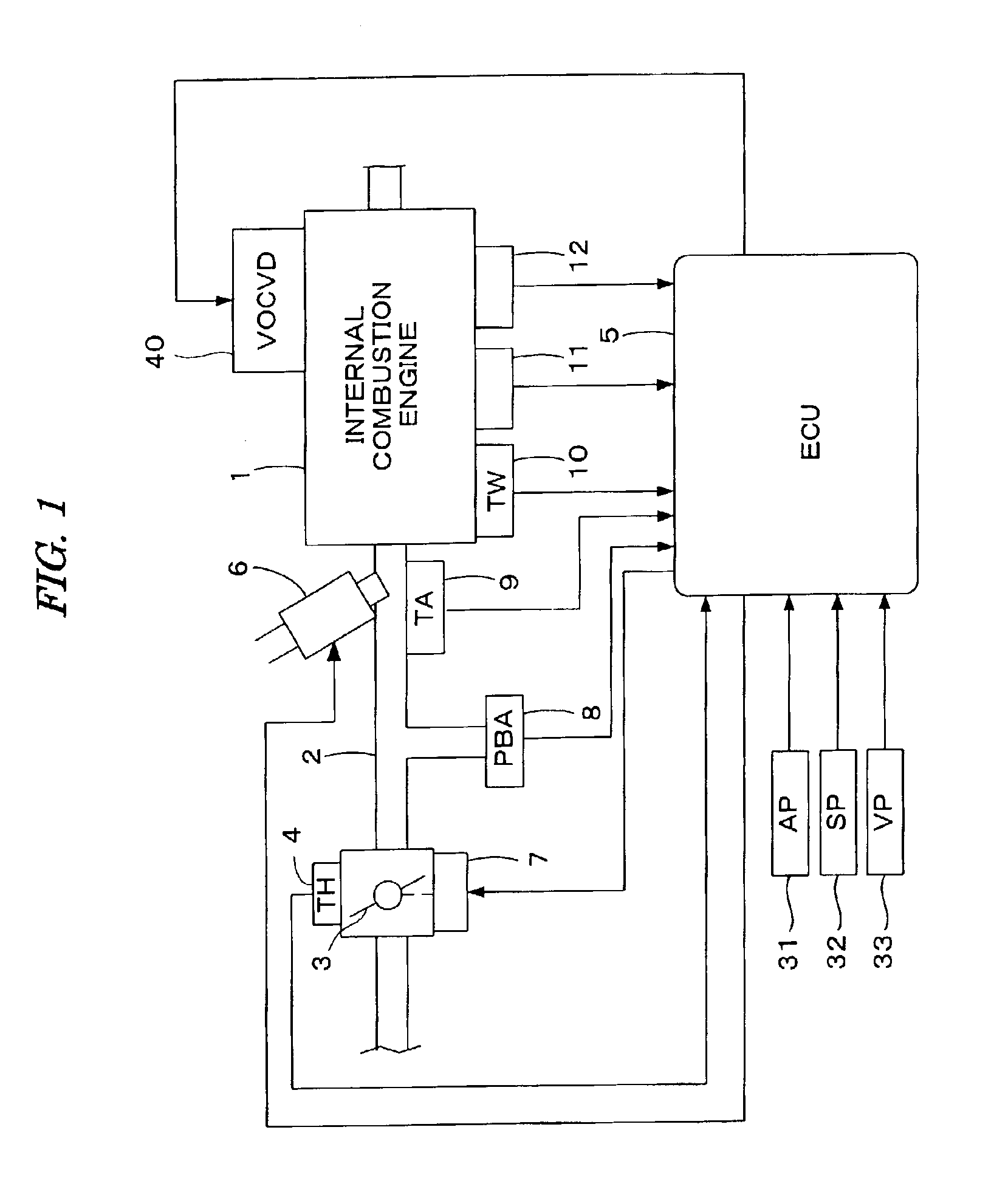
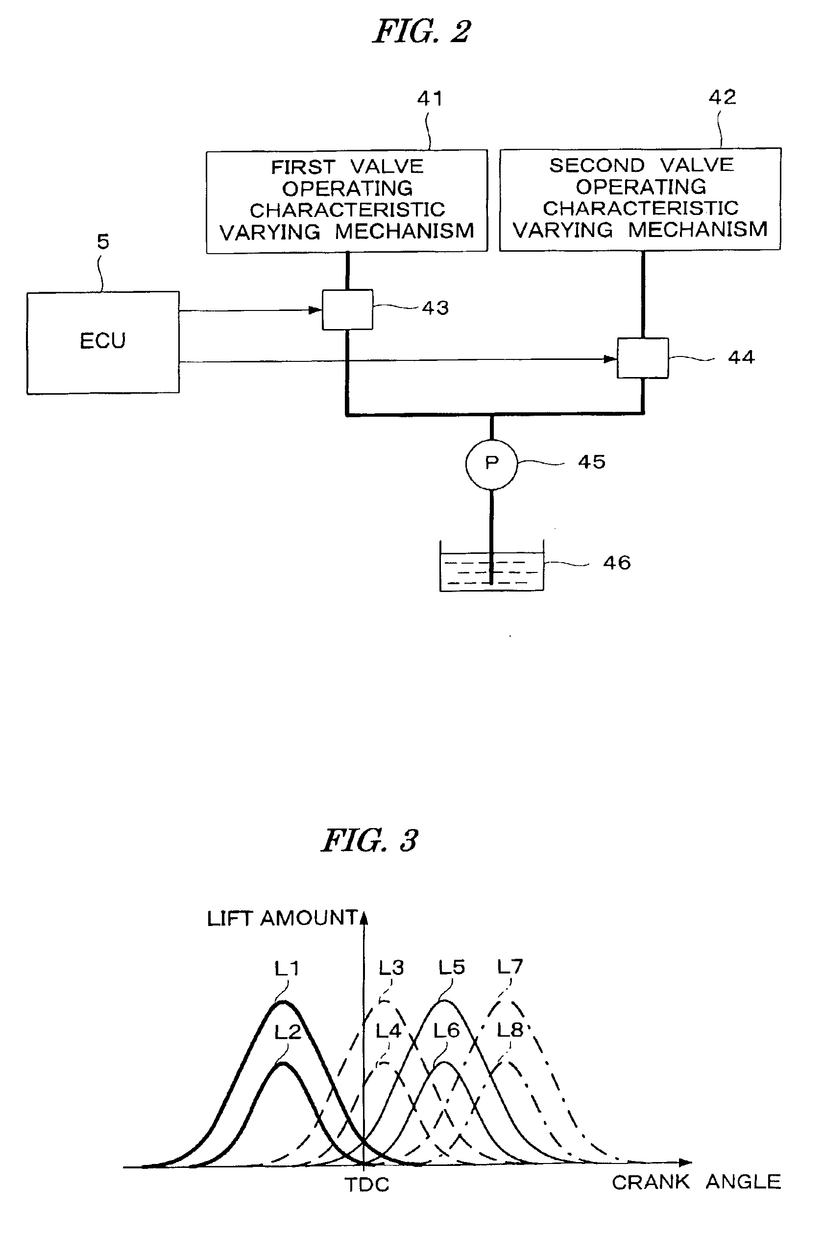
Referring to FIG. 1, there is schematically shown a general configuration of an internal combustion engine (which will be hereinafter referred to simply as “engine”) and a control system therefor according to a preferred embodiment of the present invention. FIG. 2 is a block diagram showing the configuration of a valve operating characteristic varying device 40 (VOCVD) shown in FIG. 1. The engine is a four-cylinder engine 1, for example, and it has intake valves (not shown), exhaust valves (not shown), and cams (not shown) for driving the intake valves and the exhaust valves. The engine 1 is provided with a valve operating characteristic varying device 40 having a first valve operating characteristic varying mechanism 41 and a second valve operating characteristic varying mechanism 42. The first valve operating characteristic varying mechanism 41 switches valve lift amounts and openi...


PUM


Abstract

A control system for an internal combustion engine having at least one intake valve and at least one exhaust valve is disclosed. The control system includes a valve operating characteristic varying mechanism and a hydraulic control valve for controlling a hydraulic pressure to be supplied to the valve operating characteristic varying mechanism. The valve operating characteristic varying mechanism continuously varies an operating phase of the at least one intake valve and / or the at least one exhaust valve of the engine. A cleaning operation of the hydraulic control valve is performed in a predetermined operating condition of the engine. An intake air amount of the engine is controlled according to an operating condition of the valve operating characteristic varying mechanism when the cleaning operation of the hydraulic control valve is performed.

Description

BACKGROUND OF THE INVENTIONThe present invention relates to a control system for an internal combustion engine having a valve operating characteristic varying mechanism for continuously varying an operating phase (valve timing) of intake valves and / or exhaust valves.A control system for an internal combustion engine having a valve operating characteristic varying mechanism for continuously varying an operating phase of intake valves and / or exhaust valves is described in Japanese Patent Laid-open No. 2000-104571, for example. In the control system described in this publication, a cleaning operation is performed to remove foreign matter deposited to a hydraulic control valve for controlling a hydraulic pressure to be supplied to the valve operating characteristic varying mechanism. This cleaning operation is performed by alternately supplying a maximum current and a minimum current for driving the hydraulic control valve when a vehicle is decelerated by an engine brake or when the fue...

Claims


Application Information

Patent Timeline
Patent Type & Authority Patents(United States)
IPC IPC(8): F02D41/00F02D13/02F01L1/344F02D41/22F02D41/12F02D43/00F02D41/04
CPCF01L1/344F02D13/0207F02D13/0253F01L2001/3443F01L2800/00Y02T10/18F02D41/123F02D41/221F02D2041/001Y02T10/12
Inventor TACHIBANA, YOSUKEYAMAZAKI, EISEIHASHIMOTO, EIJI
Owner HONDA MOTOR CO LTD
Why Eureka
Try Eureka