Flow meter

a flow meter and flow rate technology, applied in the direction of machines/engines, electrical control, instruments, etc., can solve the problems of no processing means for computing volumetric flow rate, no means for indicating,

Inactive Publication Date: 2005-04-05
COMBUSTION DYNAMICS
View PDF6 Cites 439 Cited by
  • Summary
  • Abstract
  • Description
  • Claims
  • Application Information

AI Technical Summary

Problems solved by technology

Further, no processing means for computing volumetric flow rate is described, and no means for indicating the direction of the velocity is described.

Method used


Image

  • Flow meter
  • Flow meter
  • Flow meter

Examples


Embodiment Construction

Detailed embodiments of the present invention are disclosed herein; however, it is to be understood that the disclosed embodiments are merely illustrative of the invention that may be embodied in various forms. In addition, each of the examples given in connection with the various embodiments of the invention are intended to be illustrative, and not restrictive. Further, the figures are not necessarily to scale, some features may be exaggerated to show details of particular components. Therefore, specific structural and functional details disclosed herein are not to be interpreted as limiting, but merely as a representative basis for teaching one skilled in the art to variously employ the present invention.

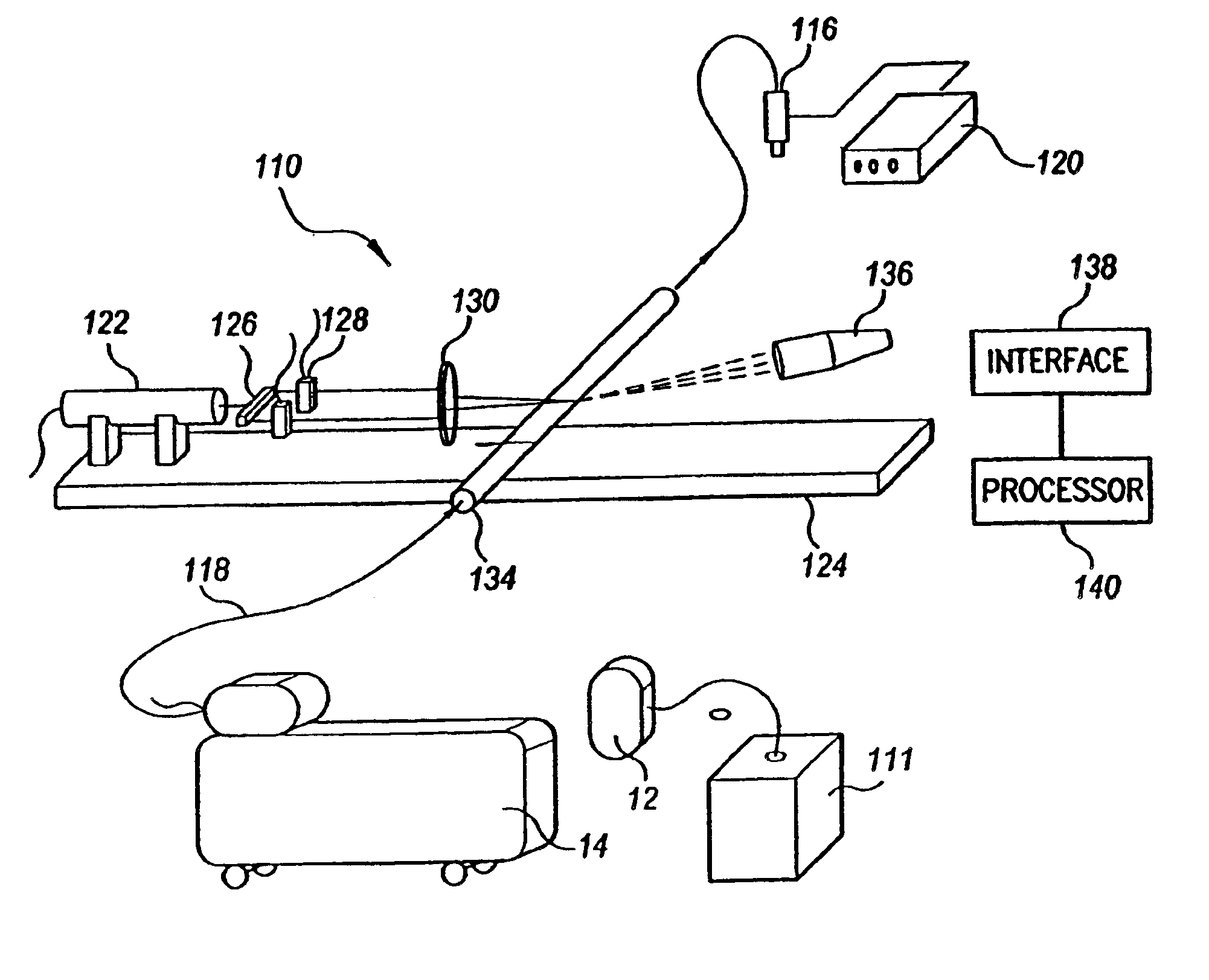
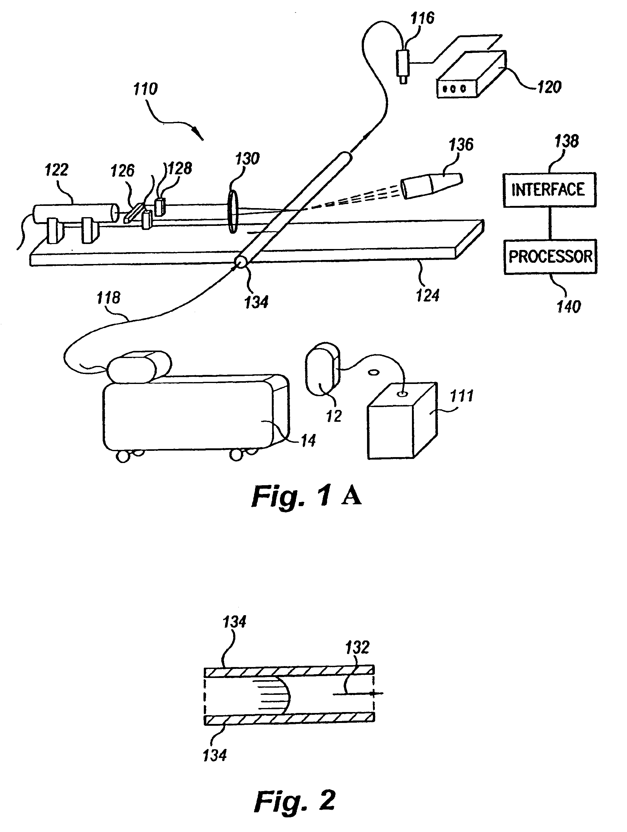
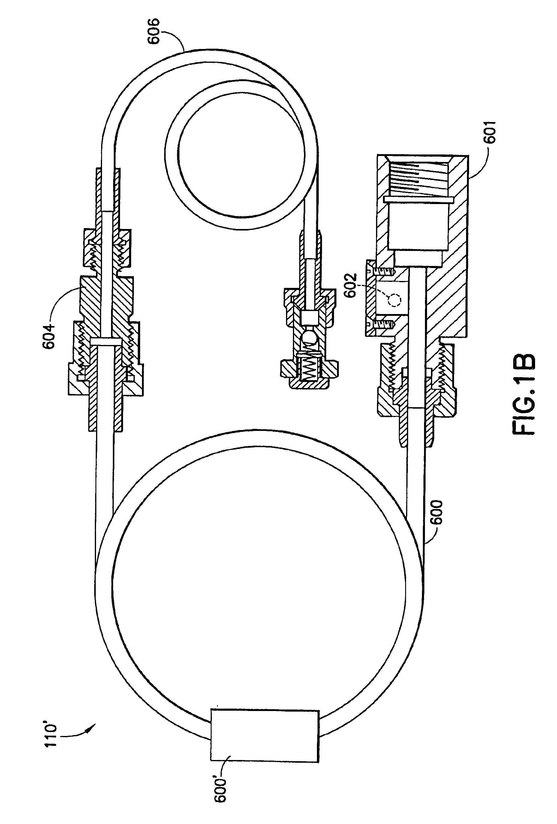
In one embodiment an on-board flow meter for installation in a fuel pipeline of a fuel injection engine is provided, comprising: (a) a measurement tube adapted for installation in a fuel pipeline of a fuel injection engine; (b) a laser-Doppler anemometer generating a pair of laser...


PUM


Abstract

Various embodiments of the present invention provide a flow meter device having a laser Doppler anemometer (LDA) which measures the instantaneous center line velocity of fluid flow in a pipe. The flow meter may process the instantaneous velocity so obtained to compute the volumetric flow rate, mass rate, and / or other flow characteristics (e.g., as instantaneous quantities and / or integrated over a time interval) The flow meter may use an electronic processing method. The electronic processing method may provide essentially an exact solution to the Navier-Stokes equations for any periodically oscillating flow.

Description

FIELD OF THE INVENTIONVarious embodiments of the present invention relate to flow meters (e.g., for measuring the flow of fluid through a conduit). In one example (which example is intended to be illustrative and not restrictive) the flow meters described may be adapted for measuring the volumetric flow rate for a high pressure direct injection automotive fuel injection system. Also described are software methods of determining the volumetric flow rate for a periodic oscillating flow in a pipe from measurement of the instantaneous center line velocity.BACKGROUND OF THE INVENTIONIn automotive fuel injection systems, the power delivered by the engine is related to the shape of the spray, as well as the quantity and timing of fuel delivered to the combustion chamber.Various devices for measuring fluid flow characteristics, at various points in the flow, have been described previously. For example:U.S. Pat. No. 3,338,093, issued Aug. 29, 1967 to J. D. Usry et al. relates to an injectant...

Claims


Application Information

Patent Timeline
Patent Type & Authority Patents(United States)
IPC IPC(8): F02M61/16F02M65/00F02M55/02F02M61/18F02M61/00F02M63/00F02D41/40F02M51/06G01F1/66G01F1/76G01F1/86F02B75/12F02B75/00
CPCF02M51/0678F02M55/02F02M61/163F02M61/18F02M63/00F02M65/00G01F1/661G01F1/86F02D41/40F02B2075/125Y02T10/123F02D2041/288F02D2041/389F02D2200/0614F02M2200/24Y02T10/44Y02T10/12Y02T10/40
Inventor ISMAILOV, MURAD M.
Owner COMBUSTION DYNAMICS
Why Eureka
Try Eureka