Oscillating flow micromixer

A micro-mixer, oscillating flow technology, applied in the direction of shaking/oscillating/vibrating mixers, mixers, chemical instruments and methods, etc., can solve the problems of smaller liquid contact area, reduced mixing effect, weakened mixing effect, etc. Enhanced mixing, low processing cost, good mixing effect

Active Publication Date: 2017-06-13
NANJING UNIV OF SCI & TECH
View PDF4 Cites 2 Cited by
  • Summary
  • Abstract
  • Description
  • Claims
  • Application Information

AI Technical Summary

Problems solved by technology

(A.Alam, K.Y.Kim, Mixing performance of a planar micromixer with circular chambers and crossing constriction channels, Sensor Actuat B-Chem, 176 (2013) 639-652.) But the mixing effect of this structure will weaken as the viscosity increases, That is, the Reynolds number Re<50, the mixing effect is significantly reduced
[0006] In addition, the use of oscillating flow can also improve fluid mixing (H.M.Xia, Z.P.Wang, W.Fan, A.Wijaya, W.Wang, Z.F.Wang, Converting steady laminar flow to oscillatory flowthrough a hydroelasticity approach at microscales, Lab Chip , 12(2012) 60-64; H.M.Xia, Z.P.Wang, V.B.Nguyen, S.H.Ng, W.Wang, F.Y.Leong, D.V.Le, Analyzing the transition pr

Method used


Image

  • Oscillating flow micromixer
  • Oscillating flow micromixer
  • Oscillating flow micromixer

Examples


Embodiment 1

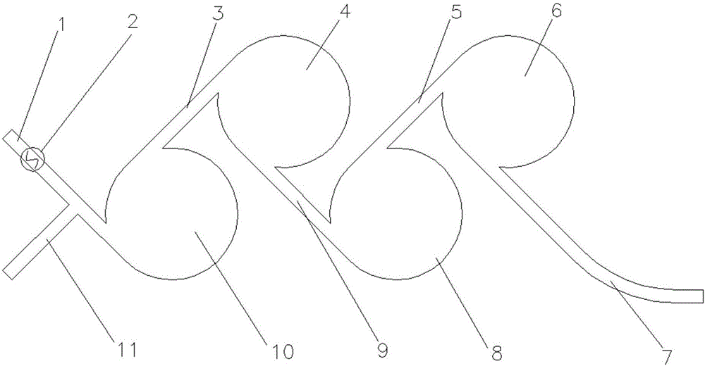
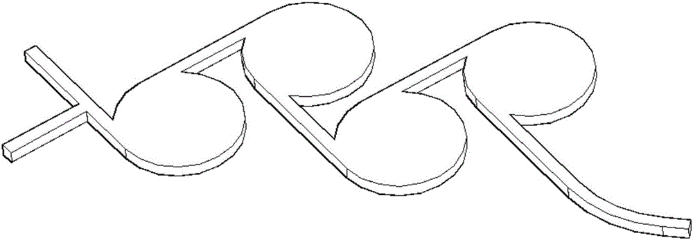
[0035] combine figure 1 , figure 2 , an oscillating flow micromixer with two inlet channels, comprising a first inlet channel 1, a second inlet channel 11, an oscillator 2, a first circular chamber 10, a first connecting channel 3, a second circular chamber 4. The second connecting channel 9, the third circular chamber 8, the third connecting channel 5, the fourth circular chamber 6, and the outlet channel 7;

[0036] The first inlet channel 1 and the second inlet channel 11 are used as two inlets of liquid flowing into the first circular chamber 10, the first inlet channel 1 is tangent to the outer circle of the first chamber 10, and the second inlet channel 1 is tangent to the outer circle of the first chamber 10. The inlet channel 11 communicates with the first inlet channel 1; the first connecting channel 3 connects the first circular chamber 10 and the second circular chamber 4, and the first connecting channel 3 communicates with the first circular chamber 10 and the s...

Embodiment 2

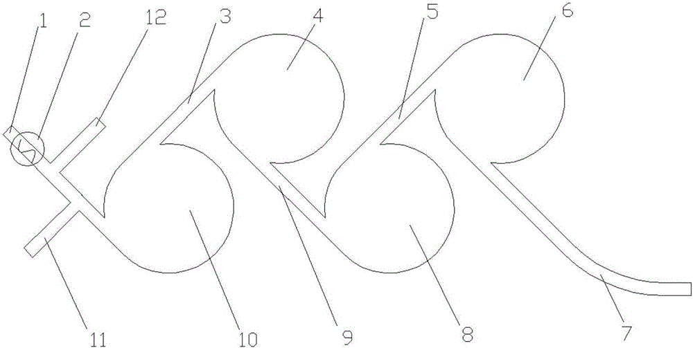
[0041] combine image 3 , an oscillating flow micro-mixer with three inlet channels, comprising a first inlet channel 1, a second inlet channel 11, a third inlet channel 12, an oscillator 2, a first circular chamber 10, a first connecting channel 3, The second circular chamber 4, the second connecting channel 9, the third circular chamber 8, the third connecting channel 5, the fourth circular chamber 6, and the outlet channel 7;

[0042] The third inlet channel 12 communicates with the first connecting channel, and the connection methods of the other inlet channels, the oscillator 2 , the circular chamber, the connecting channel and the outlet channel 7 are the same as those in the second embodiment.

[0043] combine Figure 4 , a graph of the relationship between the maximum viscosity of the liquid and the depth of the second chamber of the oscillator for an oscillatory flow micromixer of the present invention. The vertical axis on the left is the viscosity range that the o...


PUM


Abstract

The invention discloses an oscillating flow micromixer which comprises an oscillator, an inlet channel, circular chambers, connecting channels and an outlet channel; the oscillator, the inlet channel, the circular chambers, the connecting channels and the outlet channel are positioned in the same one plane; the oscillator is arranged at the inlet channel; a first inlet channel is tangentially connected with the first circular chamber, the first connecting channel is tangential to the first circular chamber and the second circular chamber, and the position of the first connecting channel is positioned at the position close to the oscillator; the remaining connecting channels are sequentially tangential to the excircles of the two circular chambers which are connected, and the remaining connecting channels are perpendicular to the front connecting channel and are positioned between the connected circular chambers and the front circular chamber; the outlet channel is tangential to the excircle of the last circular chamber, is perpendicular to the cth connecting channel and positioned between the last two circular chambers. The micromixer is applicable to mixing of high-flow fluid with wide viscosity range, and has better universality.

Description

technical field [0001] The invention belongs to microfluidic devices, in particular to an oscillating flow micromixer. Background technique [0002] Microfluidics is an interdisciplinary science and technology involving precision machinery, fluid mechanics, biomedicine, chemistry, etc. It is widely used in biochemical analysis, medical diagnosis, drug screening, etc., and has high efficiency and required Due to the advantages of fewer samples / reagents and convenient miniaturization of instruments and equipment, it has achieved rapid development in recent years. Microfluidic mixing enhancement is a key issue in the research of microfluidic technology. At low scales, the inertial forces of the liquid weaken and the viscous forces gradually increase, making mixing difficult, while at the same time, when the liquid is highly viscous, mixing becomes more difficult. Common micromixer designs are divided into two types: active and passive. [0003] Active mixing uses external fo...

Claims


Application Information

Patent Timeline
IPC IPC(8): B01F11/00B01F15/00
CPCB01F31/00B01F35/52
Inventor 吴嘉炜夏焕明
Owner NANJING UNIV OF SCI & TECH
Why Eureka
Try Eureka