

Substrate cleaning apparatus
a cleaning apparatus and substrate technology, applied in the direction of cleaning process and apparatus, cleaning apparatus, chemistry apparatus and processes, etc., can solve the problems of inability to perform high-accuracy cleaning, inability to clean substrates efficiently, and inability to achieve high-accuracy cleaning, etc., to achieve efficient cleaning of substrates, excellent chemical resistance, and effective cleaning
- Summary
- Abstract
- Description
- Claims
- Application Information
AI Technical Summary
Benefits of technology
Problems solved by technology
Method used
Image

Examples
example 1
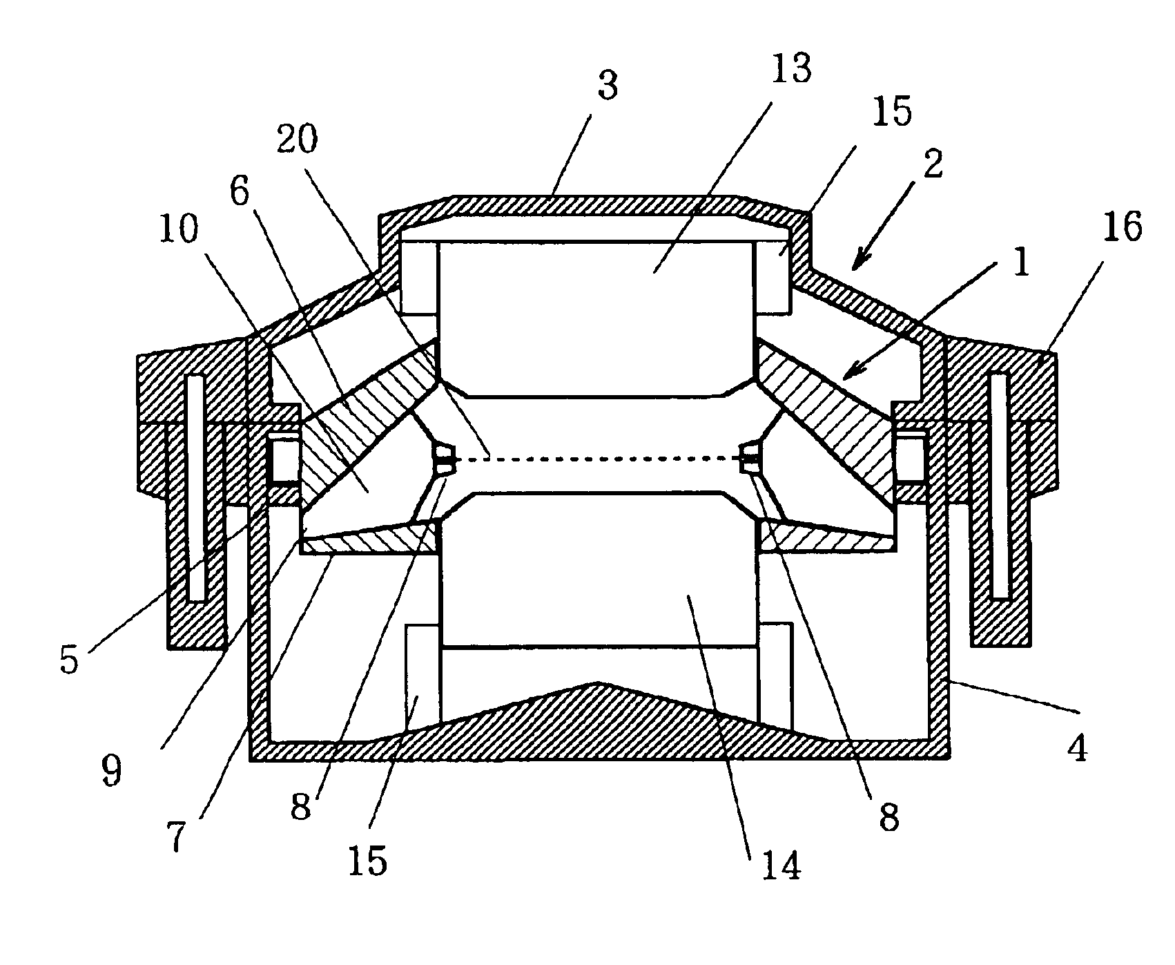
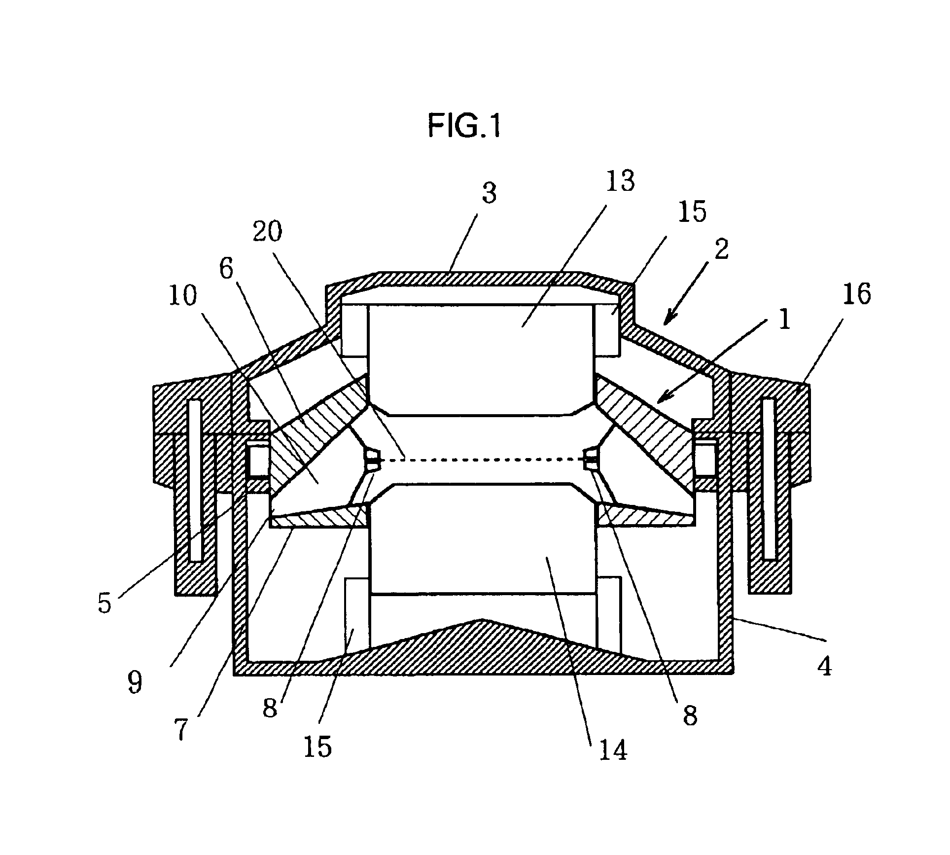
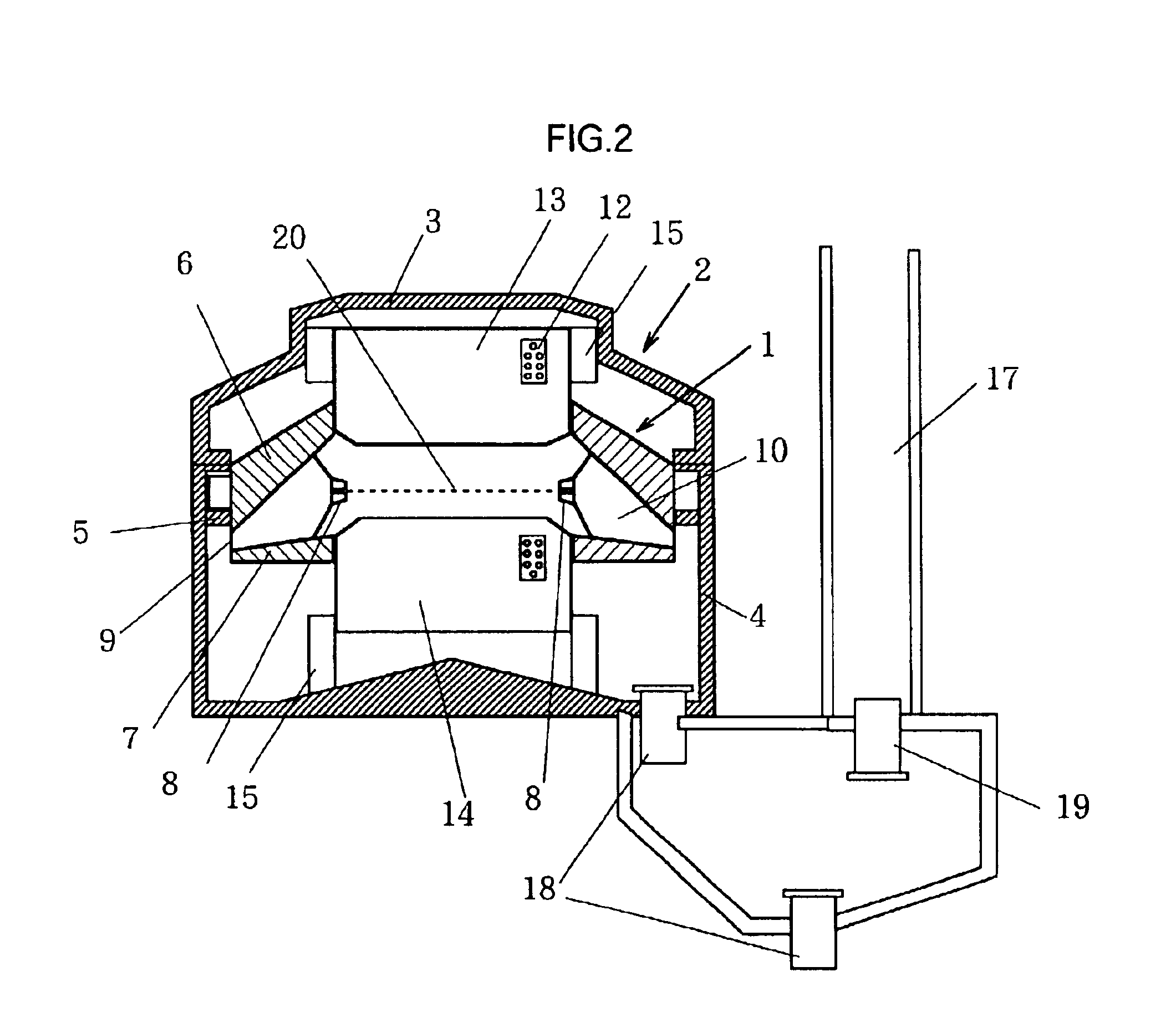
A CVD (chemical vapor deposition) process may include such a step that subsequent to formation of a Ti film on a substrate, a W film is formed successively. In a subsequent cleaning step, it may be desired, in some instances, to eliminate adhered Ti or W contaminant from the edge and back side of the substrate without dissolving the surface W film or the Ti film lying under the W film. In this Example, the apparatus of the present invention was applied to the cleaning step. For use in the cleaning, an 8-inch silicon substrate with 10-nm thick thermal oxidation SiO2 films formed on both sides thereof was fabricated and provided. The substrate was subjected to etching such that the substrate was selectively etched on only the back side and edge thereof. The substrate cleaning apparatus had the construction described above with reference to FIGS. 1 through 4A, and was provided at six locations with holding members constructed as illustrated in FIG. 6.
The substrate was placed in the inn...
PUM
 Abstract
Description
Claims
Application Information