Hydrodynamic bearing

a bearing and hydrodynamic technology, applied in the direction of cleaning process and apparatus, cleaning using liquids, separation process, etc., can solve the problem of pushing some of the filtered debris

Inactive Publication Date: 2005-04-05
ZODIAC POOL SYST LLC
View PDF9 Cites 53 Cited by
  • Summary
  • Abstract
  • Description
  • Claims
  • Application Information

AI Technical Summary

Benefits of technology

It is an object of the present invention to provide a self-cleaning filter of the cartridge type which allows easy cleaning of the cartridge filter element.
It is a further object of the present invention to provide a cartridge type filter which enables the cartridge filter element to be cleaned without having to physically remove it from the filter.

Problems solved by technology

Cleaning in this manner with a garden hose also has a disadvantage in that the force of the applied water pushes some of the filtered debris deeper into the filter medium of the longitudinal pleat folds, since the build up of filtered debris typically occurs at the outer diameter of the filter cartridge.
Periodical cleaning of the filter cartridges is important since a cartridge filter that sits dirty too long, dries and becomes impacted with filtered debris and cannot be cleaned.

Method used


Image

  • Hydrodynamic bearing
  • Hydrodynamic bearing
  • Hydrodynamic bearing

Examples


Embodiment Construction

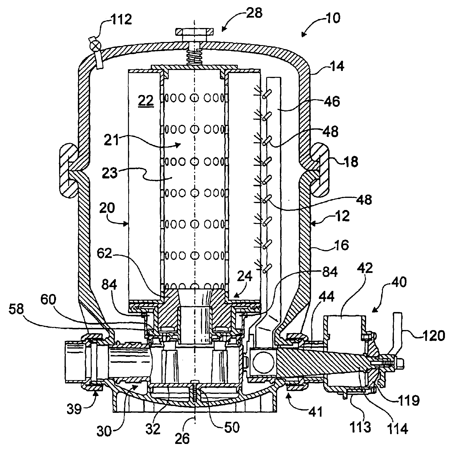
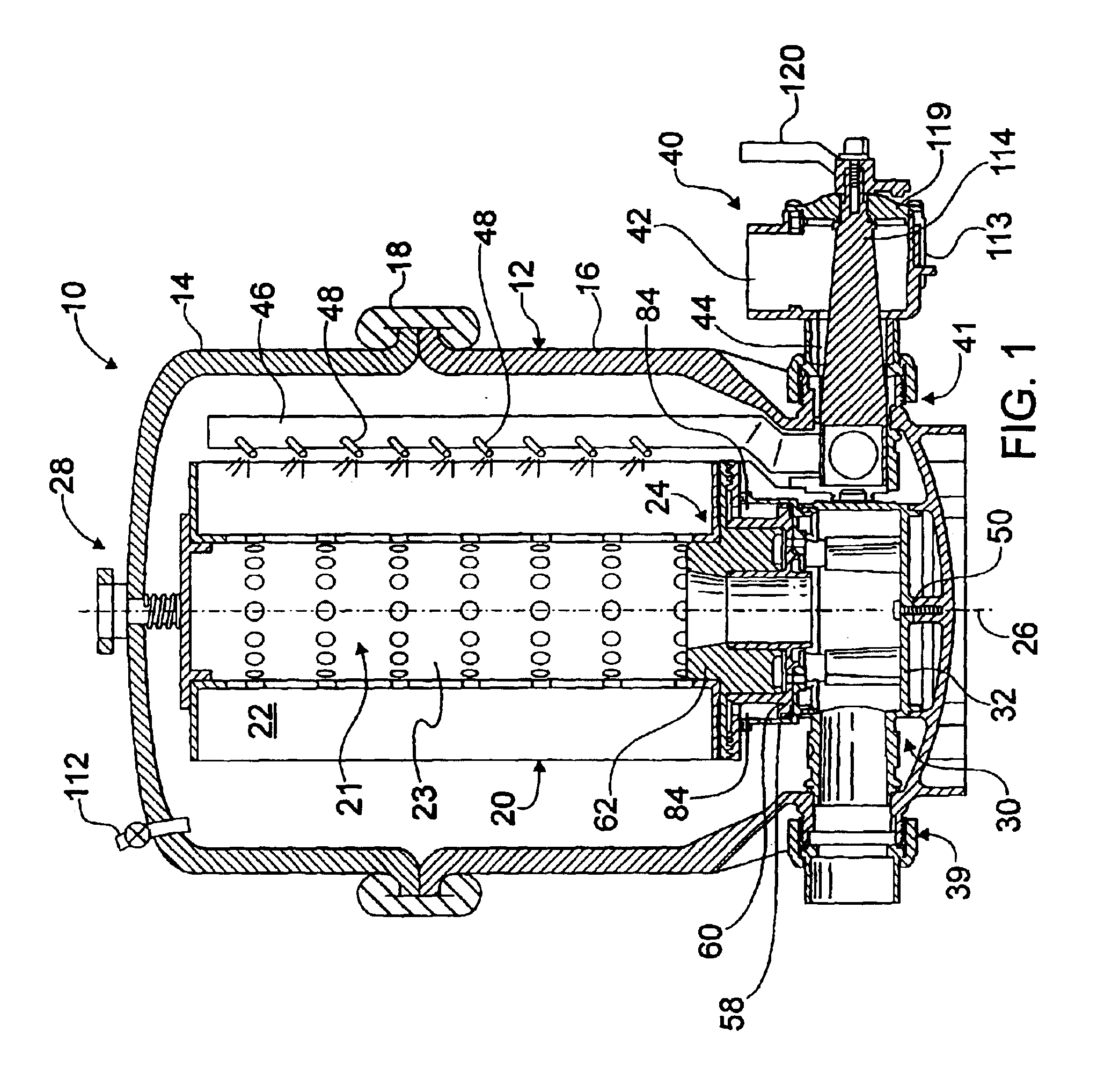
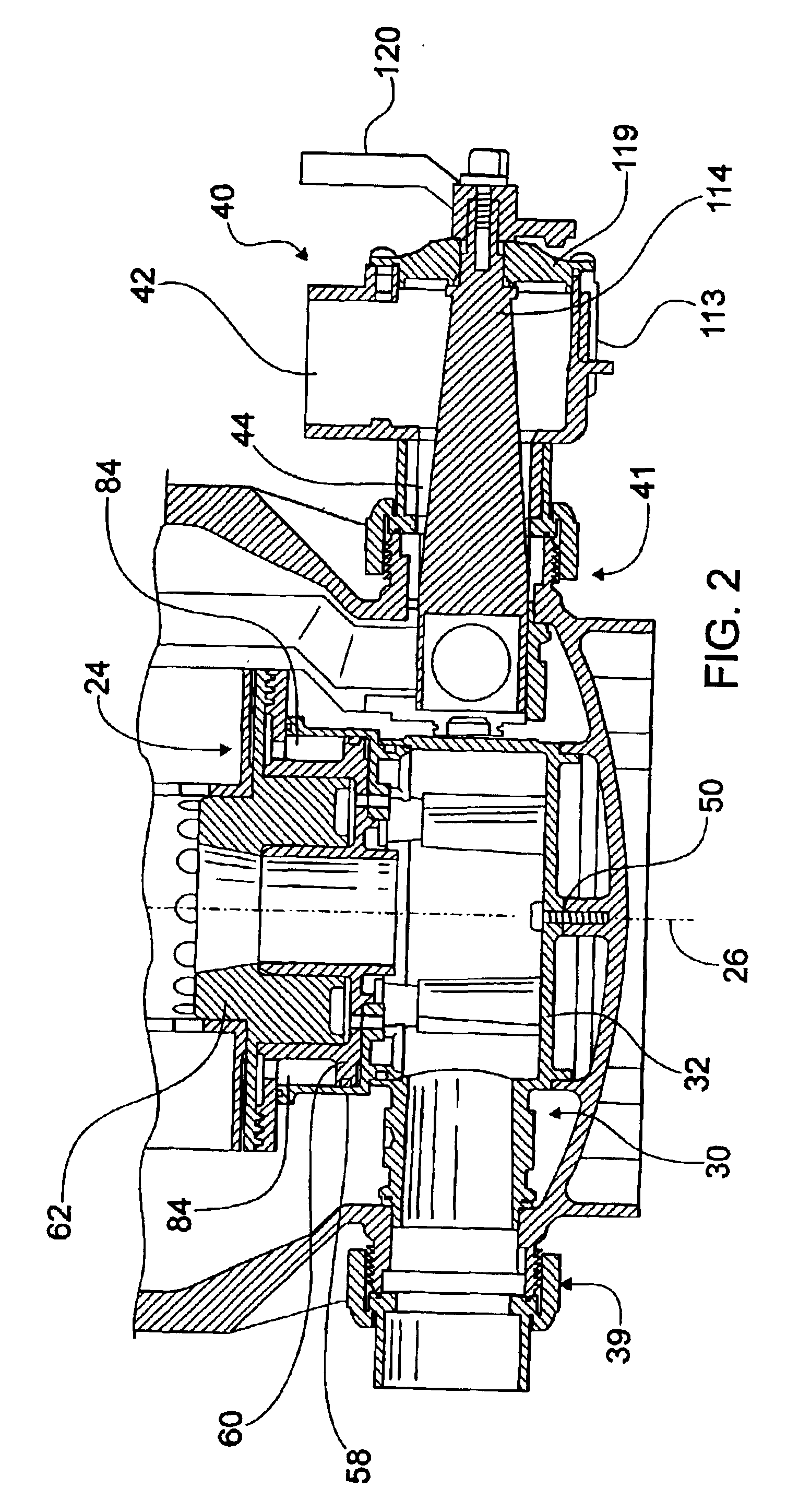
FIGS. 1-2 illustrate a self-cleaning water filter, shown generally at 10, in accordance with the present invention. The water filter 10 includes a filter housing 12 having upper 14 and lower 16 filter housings joined together by a band clamp 18, or other conventional joining devices, extending around the full circumference thereof.

The filter 10 is of the cartridge type and includes a cartridge filter element 20 in the general shape of a cylinder having a hollow interior shown at 21. The filter cartridge 20 includes longitudinal pleated folds of filter material 22 supported on a perforated tube 23 opening into the hollow interior 21. A bottom end of the filter cartridge 20 is annually supported on a hydrodynamic bearing 24 allowing free rotation of the filter cartridge 20 about its longitudinal axis 26. A spindle 28 attached to the top center of the upper filter housing 14 biases the filter cartridge 20 against the hydrodynamic bearing 24 and allows the filter cartridge 20 to rotate ...


PUM

PropertyMeasurementUnit
rotationaaaaaaaaaa
radial dynamic pressureaaaaaaaaaa
axial dynamic pressureaaaaaaaaaa

Abstract

A self-cleaning filter assembly includes a cylindrical cartridge filter element supported on a coaxially mounted hydrodynamic bearing for rotation of the cartridge filter element about its longitudinal axis. The cylindrical cartridge filter element includes a hollow interior for receiving filtered water. A water spray manifold is provided proximate to the cartridge filter element and includes spray nozzles for providing a water spray capable of rotating the cartridge filter element about its longitudinal axis. A diverter valve receives flow of water to be filtered. With the diverter valve in a first position, the received flow of water submerges the cartridge filter element, with the filtered water received at the hollow interior of the cartridge filter element. With the diverter valve, in a second position, the received flow of water is provided to the water spray manifold causing it to fill under pressure. Water sprays out of the spray nozzles directed at the cartridge filter element causing it to rotate about its longitudinal axis. The water spray cleans the cartridge filter element as it rotates. Additionally, with the diverter valve in its second position, a portion of the water flow to the water spray manifold is tapped off and provided to the hydrodynamic bearing to provide a film of water as the load bearing component allowing rotation of the cartridge filter element thereon.

Description

FIELD OF THE INVENTIONThe present invention is directed toward filters for liquids and, more particularly, toward a self-cleaning water filter for use in swimming pools and the like.BACKGROUND OF THE INVENTIONSwimming pools typically use a filtration process to remove dirt and other foreign particles which accumulate in the pool water. The pool water is pumped by a variety of known means to a filter which removes the dirt and other solid particles from the pool water. Filtered pool water is then discharged from the filter directly back to the pool. In addition to making the pool water visually appealing, removal of foreign particles by filtration helps in decreasing the disinfectant demand, typically chlorine, of the pool water necessary for killing disease causing bacteria. Typically, five basic types of filter systems are utilized for swimming pools, namely, pressure sand, pressure diatomaceous earth, vacuum diatomaceous earth, gravity sand, and cartridge type filters.As the filtr...

Claims


Application Information

Patent Timeline
Patent Type & Authority Patents(United States)
IPC IPC(8): B01D29/21B01D29/13B01D35/14B01D35/157
CPCB01D29/21B01D35/157B01D29/6446
Inventor CLARY, ROBERT S.
Owner ZODIAC POOL SYST LLC
Why Eureka
Try Eureka