Suction filter

a technology of suction filter and fabric bag, which is applied in the direction of filtration separation, machine/engine, separation process, etc., can solve the problems of easy wear and tear of the lower surface of the filtering fabric bag db>9/b>, difficult to accurately and firmly laminate, and easy to be carried out accurately and positively, without creases and lines, and without the risk of the filtering fabric bag being worn ou

Inactive Publication Date: 2005-04-05
NIFCO INC
View PDF4 Cites 7 Cited by
  • Summary
  • Abstract
  • Description
  • Claims
  • Application Information

AI Technical Summary

Benefits of technology

In other words, in the suction filter according to the present invention, since the synthetic resin upper plate is integrally molded with the upper filtering fabric constituting the filtering fabric bag and the inlet pipe is connected to the upper plate, there is no risk of the filtering fabric bag coming off the inlet pipe. Also, since the synthetic resin lower plate is integrally molded with the lower filtering fabric constituting the filtering fabric bag and the spring is fixed to the lower plate, the lower plate is pressed against a bottom surface of the fuel tank by the spring and there is no risk of the filtering fabric bag being worn out. Further, the spring is fixed between the upper and lower plates integrally provided to the upper and lower filtering fabrics, respectively, and the upper and lower filtering fabrics are connected with a specific positional relationship. Thus, when the peripheral portions of the upper and lower filtering fabrics are thermally bonded together to form the filtering fabric bag, lamination of the peripheral portions of the upper and lower filtering fabrics can be easily carried out accurately and positively, so that the filtering fabric bag can be easily and securely formed by bonding together the peripheral portions of the upper and lower filtering fabrics without making creases and lines thereon and with good productivity.

Problems solved by technology

1. Since the upper filtering fabric d3 is sandwiched between the flange d2 and the clip d5 to fix the filtering fabric bag d9 to the pipe portion d1, the filtering fabric bag d9 is liable to be disconnected;
2. Since the lower surface of the filtering fabric bag d9 is directly pressed against the bottom of the fuel tank due to the resilient force of the coil spring d7, there is a risk that the lower surface of the filtering fabric bag d9 wears out; and
3. When the upper filtering fabric d3 and the lower filtering fabric d8 are thermally bonded together to form the filtering fabric bag d9, it is hard to accurately and firmly laminate the peripheral portions thereof and set them onto a thermal bonding machine due to the resilient force of the coil spring d7. Thus, creases and lines may be formed on the filtering fabric bag d9 and the peripheral portions of both filtering fabrics d3, d8 may not be thermally bonded together firmly.

Method used


Image

  • Suction filter
  • Suction filter
  • Suction filter

Examples


first embodiment

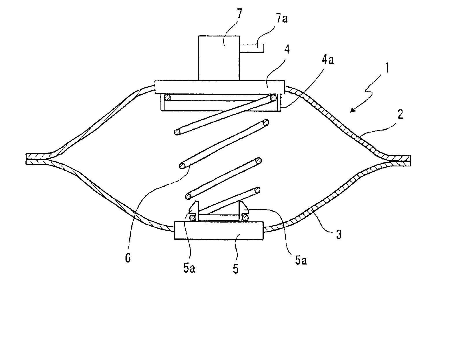
FIG. 1 is a sectional view showing a suction filter of the first embodiment according to the present invention. The suction filter is attached to a lower end of a pump b disposed in a fuel tank a so that a lower end surface thereof contacts a bottom surface of the fuel tank a, as in a suction filter d shown in FIG. 5.

In FIG. 1, reference numeral 1 represents a filtering fabric bag, wherein the respective peripheral portions of an upper filtering fabric 2 and a lower filtering fabric 3 are thermally bonded together. An upper plate 4 and a lower plate 5 made of a synthetic resin are integrally molded with the filtering fabrics 2 and 3 at the central portions thereof, and a coil spring 6 is provided between the upper and lower plates 4, 5.

Both the upper and lower plates 4, 5 are integrally molded with the filtering fabrics 2, 3 by an insert molding method. The molding materials of the respective plates 4, 5 pass through the textures of the filtering fabrics 2, 3, so that the central po...

second embodiment

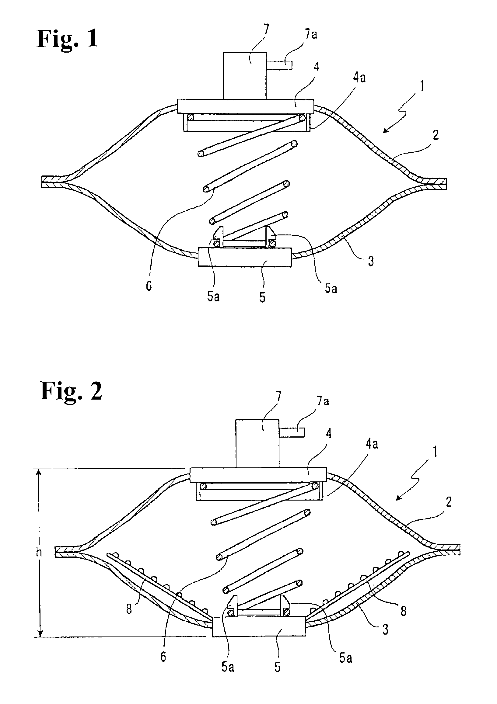
FIG. 2 is a sectional view showing a suction filter of a second embodiment according to the present invention. The suction filter includes sticking prevention members 8 integrally projecting in the filtering fabric bag 1 from an inner peripheral portion of the lower plate 5.

The sticking prevention members 8 are vertically swingably attached at their base end portions, and a plurality of small projections is integrally provided on the upper surfaces thereof. Incidentally, although only the two sticking prevention members 8 are shown in FIG. 2, actually, three or more than four sticking prevention members 8 may be disposed radially around the lower plate 5.

According to the suction filter as shown in FIG. 2, the sticking prevention members 8 can positively prevent the upper and lower filtering fabrics 2, 3 from sticking to each other so that a suction pressure becomes higher. More specifically, when a height h of the filtering fabric bag 1 becomes low due to the installation state of t...

third embodiment

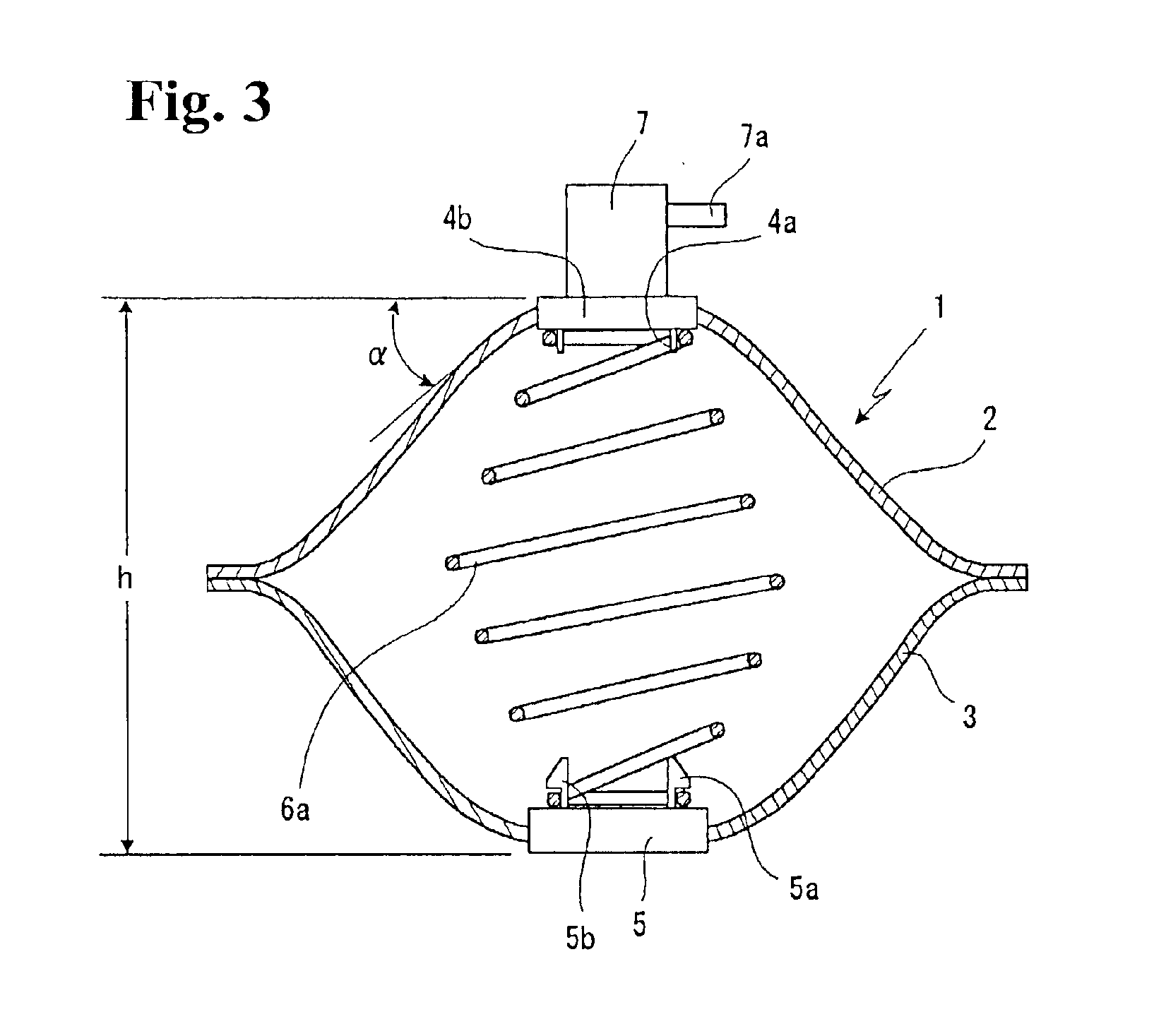
FIG. 3 is a sectional view showing a suction filter of the third embodiment according to the present invention. The suction filter includes a coil spring 6a formed to be big at an intermediate portion in an axial direction and small at both end portions thereof, and upper and lower plates 4b, 5 formed to be relatively small.

According to the suction filter as shown in FIG. 3, since both end portions of the coil spring have relatively small diameters, the upper and lower plates 4b, 5 can also be formed relatively small (the upper plate 4b can be formed smaller than those of the first and second embodiments). Therefore, even in case the height h of the filtering fabric bag 1 is made larger, the filtering fabric bag 1 can be effectively prevented from being creased or lined, so that a suction filter having a good performance can be positively obtained.

More specifically, in case the height of the filtering fabric bag 1 is made large, the inclination angle α is inevitably large, so that w...


PUM

PropertyMeasurementUnit
sizesaaaaaaaaaa
heightaaaaaaaaaa
elasticityaaaaaaaaaa

Abstract

In a suction filter, a synthetic resin upper plate 4 to be connected to a fuel inlet pipe is integrally molded with an upper filtering fabric 2, and a synthetic resin lower plate 5 is integrally molded with a lower filtering fabric. Two end portions of a spring are fixed to the upper and lower plates, and the peripheral portions of the upper and lower filtering fabrics are bonded together to obtain a filtering fabric bag. Thus, there is no such risk that the filtering fabric bag comes off the inlet pipe, the filtering fabric bag is worn out, and creases and poor bonding occur. Thus, the suction filter can be obtained with high reliability and good productivity.

Description

BACKGROUND OF THE INVENTION AND RELATED ART STATEMENTThe invention relates to a suction filter to be attached to a tip portion of an inlet pipe for sucking fuel in a fuel tank and feeding the fuel to an engine or the like of an automobile to filter the fuel.As shown in FIG. 5, a pump b for feeding fuel in a fuel tank a to an engine is disposed in the fuel tank of an automobile, and the fuel is sucked through an inlet pipe b1 provided to the pump b and sent to the engine through a fuel filter c.In this case, as shown in FIG. 5, a suction filter d is also attached to a tip portion of the inlet pipe b1 to remove relatively large impurities. The suction filter d is positioned to abut against a bottom surface of the fuel tank a.Heretofore, a suction filter having a structure as shown in FIG. 4 has been known. More specifically, a brim-shape flange d2 is integrally formed at a lower end portion of a pipe portion d1 to be connected to the inlet pipe b1 of the pump b; the pipe portion d1 is...

Claims


Application Information

Patent Timeline
Patent Type & Authority Patents(United States)
IPC IPC(8): B01D35/00B01D35/027B01D29/13B01D35/02F02M37/10F02M37/22
CPCB01D35/0273F02M2037/228F02M37/50
Inventor IWAMOTO, TAKASHI
Owner NIFCO INC
Why Eureka
Try Eureka